W2-880 Tjd, Thd, Th - Repair - Wisconsin Motors
W2-880 Tjd, Thd, Th - Repair - Wisconsin Motors
W2-880 Tjd, Thd, Th - Repair - Wisconsin Motors

You also want an ePaper? Increase the reach of your titles
YUMPU automatically turns print PDFs into web optimized ePapers that Google loves.
Starting Switch<br />
~11 STARTING SOLENOID<br />
SW~TCH<br />
Storl ing<br />
1. Visually inspect plug wires, coil wire, distributor cap and<br />
rotor. Replace any components that show deterioration. It<br />
is especially importanthat the cap and plug wires be in<br />
good condition, free of oil, grease and moisture.<br />
2. Check for loose or poor connections in ignition circuit.<br />
Check baUery terminals for corrosion and loose connections.<br />
3. Check battery voltage with engine off. It should be 12 to<br />
15 volts.<br />
If the above items have been checked and found to be proper and<br />
the engine’s distributor is believed to be faulty, the distributor<br />
should be tested.<br />
N°’l<br />
i<br />
Spark<br />
;,U~T- OUT<br />
Generator<br />
~Plugs<br />
No. 2<br />
Distributor<br />
Ammeter ~<br />
HI Temp.<br />
Safety Switch<br />
Ignition<br />
Coil<br />
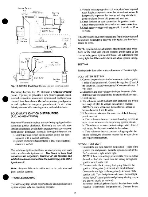
Fig. 18, WIRING DIAGRAM Battery Ignition with Generator<br />
<strong>Th</strong>e wiring diagram, Fig. 18, illustrates a negative ground<br />
circuit. If polarity of generator is for a positive ground circuit,<br />
terminal connections at ammeter, ignition coil and battery are<br />
reversed from those shown. Do notuse positive gound generator<br />
and regulator in a negative ground cirruit, or vice versa.<br />
Polarity does not affect starting motor, coil and distributor.<br />
SOLID STATE IGNITION DISTRIBUTOFIS<br />
(TJD, <strong>W2</strong>-<strong>880</strong> -YF52S1<br />
Many new<strong>Wisconsin</strong> engines are now being (Nuipped with<br />
solid state ignition distributor. Externally the new solid state<br />
ignition distributors are similar in appearance to a conventional<br />
point ignition distributor. Internally the major differences are:<br />
1. Distributor cam which opens ignition points has been<br />
replaced with a magnet assembly.<br />
2. Ignition points have been replaced with a "Hall effect type"<br />
electronic module.<br />
<strong>Th</strong>is solid state ignition distributor uses two primary wire leads<br />
which attach to the ignition coil. <strong>Th</strong>e black or blue lead<br />
connects the negative(-) terminal of the ignition coil<br />
while the red lead connects to the positiw ~. (+) side of the<br />
ignition coil.<br />
Note: the same <strong>Wisconsin</strong> coil is used on the solid state and<br />
pomt ~gnmon systems.<br />
TROUBLESHOOTING<br />
<strong>Th</strong>e following steps should be performed if the engines ignition<br />
system appears to be not operating properly:<br />
NOTE: Ignition timing adjustment specifications and procedures<br />
for the solid state ignition systems are the same as the<br />
corresponding point ignition distributor. An automotive type<br />
timing light should be used to check and adjust ignition timing.<br />
TESTING<br />
Testing can be done either with a voltmeter or a 12 volt test light.<br />
VOLT METER TESTING<br />
l. Connect the positive (+) lead of a voltmeter to the negative<br />
(-) side of the ignition coil. Ground the negative (-) lead<br />
the voltmeter. Set the voltmeter to DC volts on at least a 15<br />
volt scale.<br />
2. Disconnecthe high voltage wire from the center of the<br />
distributor cap and ground it to the engine block or chasis.<br />
3. Crank engine.<br />
4. <strong>Th</strong>e voltmeter should fluctuate from a range of 1 to 2 volts<br />
to a range of 10 to 12 volts as the engine is cranked.<br />
NOTE: On some voltmeters the needle will appear to<br />
bounce between 1 and 12 volts.<br />
5. If the voltmeter does not fluctuate, one of the following<br />
problems exist:<br />
a. If the voltmeter shows a constant 0 reading, there is an<br />
open circuit somewhere in the primary ignition circuit.<br />
b. I f the voltmeter shows a constant voltage in the 1.0 to 3.5<br />
volt range, the electronic module is shorted out.<br />
c. If the voltmeter shows a constant voltage equal to the<br />
battery voltage, the electronic module has an open circuit<br />
and requires replacement.<br />
12 VOLT TEST LIGHT<br />
1. Connect the test light between the positive (+) side of the<br />
ignition coil and ground. With the ignition switch in the<br />
"on" position the light should light.<br />
NOTE: If there is no voltage present at the positive side of<br />
the coil, recheck the circuit from the battery through the<br />
ignition switch to the coil.<br />
2. Disconnect the black primary lead going between the<br />
ignition coil negative (-) terminal and the distributor.<br />
Connect the test light to the negative (-) terminal of the<br />
!gnition coil. Turn the ignition switch on - the test light<br />
should light, if not the ignition coil primary winding is open<br />
and the coil should be replaced.<br />
Reconnect the black primary lead of the distributor to the<br />
negative (-) terminal of the ignition coil. Connect the test<br />
16