W2-880 Tjd, Thd, Th - Repair - Wisconsin Motors
W2-880 Tjd, Thd, Th - Repair - Wisconsin Motors
W2-880 Tjd, Thd, Th - Repair - Wisconsin Motors

Create successful ePaper yourself
Turn your PDF publications into a flip-book with our unique Google optimized e-Paper software.
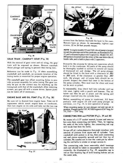
GOVERNOR<br />
GEAR<br />
OI L. ~$ P RAY P L U N .....<br />
CAMSHAFT<br />
GEAR<br />
Fig. 38<br />
screws from the bottom that hold the base to the case.<br />
Remove base as shown. In reassembly; tighten capscrews,<br />
22 to 24 foot pounds torque.<br />
Fig. 36<br />
GEAR TRAIN - CAMSHAFT GEAR (Fig. 36)<br />
With the removal of gear cover and oil sling, the gear<br />
train will be exposed as shown. Remove camshaft<br />
thrust plunger and spring to prevent their being lost.<br />
Reference can be made to Fig. 36 when assembling<br />
crankshaft and camshaft, as accurate location of the<br />
timing marks is essential for proper engine operation.<br />
<strong>Th</strong>e camshaft gear has offset mounting holes to provide<br />
accurate assembly for valve timing. <strong>Th</strong>e gear can<br />
only be put on the correct way for matching up the<br />
timingmark with that of the crankshaft. After removing<br />
screws, pry gear off with a screw driver. Spacer plate<br />
can be taken off if necessary.<br />
ENGINE BASE AND OIL PUMP (Fig. 37, Fig. 38)<br />
Be sure oil is drained from engine base. Take out 8<br />
capscrews which mount engine base to crankcase,<br />
then turn engine on its side and take out the two cap<br />
OIL PUMP<br />
ENGINE BASE<br />
Fig. 37<br />
NOTE: In engine models TH and THD, the oil pump is located<br />
toward the gear train end of the crankcase, as illustrated in Fig.<br />
37, and is mounted in place with 3 capscrews. Model TJD, <strong>W2</strong>-<br />
<strong>880</strong> pump is mounted near ~he center of the case below the oil<br />
header tube, and is held in place with 2 capscrews.<br />
Dismantle the oil pump by taking out capscrews which<br />
hold it to the crankcase. All parts of the pump should<br />
be thoroughly washed in solvent to remove all traces<br />
of thickened oil and sludge. <strong>Th</strong>e oil pump plunger<br />
should be fitted to the bore with a clearance of .003<br />
to .005 inch. If the clearance is greater than .007<br />
inch, the plunger and oil pump body should be replaced.<br />
Inspect the check ball seat in the bottom of<br />
the pump cylinder. <strong>Th</strong>is seat must be clean and must<br />
not be worn or pitted.<br />
In reassembly; drop check ball into cylinder and tap<br />
into seat, lightly with a punch and hammer. <strong>Th</strong>e retainer<br />
can then be put in place and the spring and<br />
plunger inserted into the cylinder bore.<br />
Before assembling oil pump to crankcase, fill base<br />
partially with engine oil and work pump plunger up<br />
and down, see Fig. 38, to test operation of pump.<br />
When mounting pump, be sure plunger rod and cap are in<br />
position. Plunger cap for TJD , <strong>W2</strong>-<strong>880</strong> en~ne is 9/16" long, for<br />
TH, THD -- 7/16" long.<br />
CONNECTING ROD and PISTON (Fig’s. 39 and 40)<br />
By means of a 1/2" socket wrench, loosen and remove<br />
hex nuts from connecting rod bolts. <strong>Th</strong>en, by tapping<br />
the ends of the bolts lightly, the connecting rod cap<br />
will break free from the bolts.<br />
Scrape off all carbon deposits that might interfere with<br />
removal of pistons from upper end of cylinder. Turn<br />
crankshaft until piston is at top, then push connecting<br />
rod and piston assembly upward and but thru top of<br />
cylinder. Be careful not to mar the crank pin by allowing<br />
the rod bolts to strike or scrape across it.<br />
<strong>Th</strong>e connecting rods have removable shell bearings<br />
and care should be taken in reassembly to mount them<br />
correctly. As illustrated in Fig. 39, assemble cap to<br />
rod so that locating lug of both bearing halves are on<br />
the same side.<br />
25