W2-880 Tjd, Thd, Th - Repair - Wisconsin Motors
W2-880 Tjd, Thd, Th - Repair - Wisconsin Motors
W2-880 Tjd, Thd, Th - Repair - Wisconsin Motors

You also want an ePaper? Increase the reach of your titles
YUMPU automatically turns print PDFs into web optimized ePapers that Google loves.
DISASSEMBLY<br />
Before disassembling: Clean outside of carburetor from all<br />
material<br />
When cleaning a completely assembled carburetor<br />
do not blow with compressed air, you may collapse the float.<br />
For a complete disassembly, follow the sequence of part reference<br />
numbers in the carburetor exploded view, Fig. 3. Nozzle<br />
Ref. 9, Fig. 1 is not removable.<br />
IMPORTANT: Before removing <strong>Th</strong>rottle and Choke levers, note<br />
their position and location..Optional mounting is available and<br />
may differ from exploded view i11ustration.<br />
CLEANING<br />
Wash all parts in a mild solvent or fuel. Blow air through orifices<br />
(holes) and channels in throttle body and J:’uel bowl Do<br />
not probe with any sharp tools which might .damage small<br />
metering holes.<br />
REASSEMBLY<br />
Replace all worn or damaged parts -- use all new gaskets.<br />
Note; Body Gasket (18) is put on before float is assembled,<br />
and round opening in gasket fits into groove of Venturi (11).<br />
Be sure that Notch in Venturi is facing toward float needle<br />
valve - this is clearance for Main nozzle in throtde body.<br />
ADJUSTMENTS, Fig. 1<br />
Turn Idle speed screw (S), Fig. 3~in until throttle valve<br />
slightly open. With engine warmed up and running, turn adjusting<br />
screw in or out as required to obtain desired low idle speed<br />
(I000 to 1200 r.p.m.).<br />
<strong>Th</strong>e Idle adjusting needle (14) should be seated lightly (clockwise),<br />
then backed out ] + I/8 turns as a preliminary setting.<br />
With engine warmed up and running at about 1200 R.P.M., fine<br />
tune idle mixture for smooth steady running.<br />
<strong>Th</strong>e Main Metering Jet (4), for high speed operation is fixed<br />
(not adjustable), as standard equipment, and used in the majority<br />
of engine applications. However, an Adjustable Jet carburetor<br />
is available, and the High Speed Adjustment is made by<br />
means of the Needle Assembly, Item 22A of Fig. 3, in the<br />
following manner:<br />
1. As a preliminary setting, turn needle out from its seat about<br />
1 to 11,~ turns open.<br />
2. With engine warmed up and running at idle speed, crack<br />
throttle open suddenly.<br />
3. If engine hesitates before speeding up, open Main Jet<br />
Needle 1/8 to 1/4 turn. Repeat until engine goes from idle<br />
to high speed without hesitation.<br />
\C> ~’~]9 /Optional <strong>Th</strong>rottle<br />
4 5 6 ~ r~ / Jever (e) located<br />
X<br />
\ ~ /on this side -<br />
\ \ / / Carburetor Re{. 4, S<br />
Assemble <strong>Th</strong>rottle Valve (8) and Choke Valve (25) with<br />
numbers facing to the outside, when valves are in the closed<br />
position.<br />
POR TANT: Be careful in tightening brass screw,.; and fittings,<br />
so as not to strip threads and screw driver slots.<br />
Tighten firmly<br />
but not excessively.<br />
Valve Seat (16) -- 40 to 50 inch pounds torque<br />
Main Jet (22) - 50 to 60 inch pounds torque<br />
.<br />
FLOAT SETTING, Fig. 2<br />
With fuel bowl removed and float assembly in place, turn throttle<br />
body upside down so that float assembly is on top,. Check float<br />
height with a depth gauge. Setting should be 1.010 inch -+ .020<br />
above bowl gasket. If necessary, bend float arm (at float),<br />
obtain correct height.<br />
SPRING<br />
BUOYAN E /<br />
SPRING<br />
20 21 22 ~ 36 35 34 33 3~ ~.,~<br />
~~]~ (bend location)<br />
..... @¢ ~THROTTLE<br />
BODY<br />
Fig. 2 FLOAT SETTING<br />
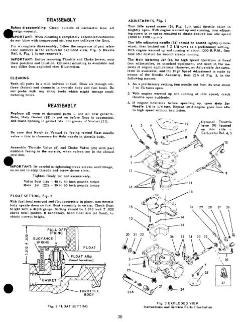
Fig. 3 EXPLODED VIEW<br />
Instructions and Service Parts Illustration<br />
36