W2-880 Tjd, Thd, Th - Repair - Wisconsin Motors
W2-880 Tjd, Thd, Th - Repair - Wisconsin Motors
W2-880 Tjd, Thd, Th - Repair - Wisconsin Motors

Create successful ePaper yourself
Turn your PDF publications into a flip-book with our unique Google optimized e-Paper software.
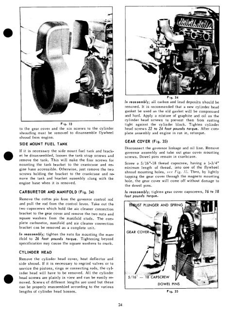
Fig. 33<br />
to the gear cover and the six screws to the cylinder<br />
shrouding must be removed to disassemble flywheel<br />
shroud from engine.<br />
SIDE MOUNT FUEL TANK<br />
If it is necessary the side mount fuel tank and bracket<br />
be disassembled, loosen the tank strap screws and<br />
remove the tank. <strong>Th</strong>is will make the four screws for<br />
mounting the tank bracket to the crankcase and engine<br />
base accessible. Otherwise, just remove the two<br />
screws holding the bracket to the crankcase and remove<br />
the tank and bracket assembly along with the<br />
engine base when it is removed.<br />
CARBURETOR AND MANIFOLD (Fig. 34)<br />
Remove the cotter pin from the governor control rod<br />
and pull the rod from the control lever. Take out the<br />
two capscrews which hold the air cleaner connection<br />
bracket to the gear cover and remove the two nuts and<br />
square washers from the manifold studs. <strong>Th</strong>e complete<br />
carburetor, manifold and air cleaner connection<br />
bracket can be removed as a complete unit.<br />
In reassembly; tighten the nuts for mounting the manifold<br />
to 26 foot pounds torque. Tightening beyond<br />
specification may cause the square washers to crack.<br />
Fig. 34<br />
In reassembly; all carbon and lead deposits should be<br />
removed. It is recommended that a new cylinder head<br />
gasket be used as the old gasket will be compressed<br />
and hard. Apply a mixture of graphite and oil on the<br />
cylinder head screws to prevent them from rusting<br />
tight against the cylinder block. Tighten cylinder<br />
head screws 22 to 24 foot pounds torque. After complete<br />
assembly and engine is run in, retorque.<br />
GEAR COVER (Fig. 35)<br />
Disconnect the governor linkage and oil line. Remove<br />
governor assembly and take out gear cover mounting<br />
screws. Dowel pins remain in crankcase.<br />
Screw a 5/16"-18 thread capscrew, having a 1o3/4"<br />
minimum length of thread, into one of the flywheel<br />
shroud mounting holes, see Fig. 35. <strong>Th</strong>en, by lightly<br />
tapping the gear cover through the magneto mounting<br />
hole, the gear cover will come off without damage to<br />
the dowel pins.<br />
In reassembly; tighten gear cover capscrews, 16 to 18<br />
foot pounds torque.<br />
J T~T PLUNGER AND SPRING<br />
CYLINDER HEAD<br />
Remove the cylinder head cover, heat deflector and<br />
side shroud. If it is necessary to regrind valves’ or to<br />
service the pistons, rings or connecting rods, the cylinder<br />
head will have to be removed. All the cylinder<br />
head screws are plainly in view and can be easily removed.<br />
Screws of different lengths are used but these<br />
can be properly reassembled according to the various<br />
lengths of cylinder head bosses.<br />
5/16" -- CAPSCREW<br />
DOWEL PINS<br />
Fig. 35<br />
24