W2-880 Tjd, Thd, Th - Repair - Wisconsin Motors
W2-880 Tjd, Thd, Th - Repair - Wisconsin Motors
W2-880 Tjd, Thd, Th - Repair - Wisconsin Motors

Create successful ePaper yourself
Turn your PDF publications into a flip-book with our unique Google optimized e-Paper software.
shown in Fig. 41. <strong>Th</strong>e word ’TOP’ on compression and<br />
scraper rings indicates direction of ring placement on<br />
piston. Spread ring only far enough to slip over piston and<br />
into correct groove, being careful not to distort ring. Assemble<br />
bottom ring first and work upward, installing top<br />
ring last. <strong>Th</strong>e outer diameter of the top compression ring is<br />
chrome plated. Mount scraper ring with scraper edge<br />
down, otherwise oil pumping and excessive oil consumption<br />
will result. Refer to Fig. 42 for correct placement of<br />
rings. Model TJD & <strong>W2</strong>-<strong>880</strong> engines have a tapered face<br />
scraper ring on the new 3 ring pistons.<br />
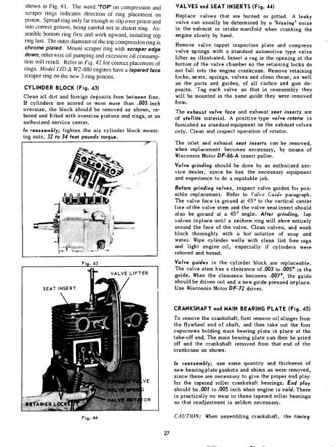
CYLINDER BLOCK (Fig. 43)<br />
Clean all dirt and foreign deposits from between fins.<br />
If cylinders are scored or worn more than .005 inch<br />
oversize, the block should be removed as shown, rebored<br />
and fitted with oversize pistons and rings, at an<br />
authorized service center.<br />
In reassembly; tighten the six cylinder block mounting<br />
nuts, 32 to 34 foot pounds torque.<br />
SEAT INSERT<br />
Fig. 43<br />
VALVE LIFTER<br />
VALVES and SEAT INSERTS (Fig. 44)<br />
Replace valves that are burned or pitted. A leaky<br />
valve can usually be determined by a ’hissing’ noise<br />
in the exhaust or intake manifold when cranking the<br />
engine slowly by hand.<br />
Remove valve tappet inspection plate and compress<br />
valve springs with a standard automotive type valve<br />
lifter as illustrated. Insert a rag in the opening at the<br />
bottom of the valve chamber so the retaining locks do<br />
not fall into the engine crankcase. Remove retaining<br />
locks, seats, springs, valves and clean these, as well<br />
as the ports and guides, of all carbon and gum deposits.<br />
Tag each valve so that in reassembly they<br />
will be mounted in the same guide they were removed<br />
from.<br />
<strong>Th</strong>e exhaust valve face and exhaust seat inserts are<br />
of stellite material. A positive type valve rotator is<br />
furnished as standard equipment on the exhaust valves<br />
only. Clean and inspect operation of rotator.<br />
<strong>Th</strong>e inlet and exhaust seat inserts can be removed,<br />
when replacement becomes necessary, by means of<br />
<strong>Wisconsin</strong> Motor DF-66-A insert puller.<br />
Valve grinding should be done by an authorized service<br />
dealer, since he has the necessary equipment<br />
and experience to do a reputable job.<br />
Before grinding valves, inspect valve guides for possible<br />
replacement. Refer to Valve Guide paragraph.<br />
<strong>Th</strong>e valve face is ground at 45 ° to the vertical center<br />
line of the valve stem and the valve seatinsert should<br />
also be ground at a 45 ° angle. After grinding, lap<br />
valves in place until a uniform ring will show entirely<br />
around the face of the valve. Clean valves, and wash<br />
block thoroughly with a hot solution of soap and<br />
water. Wipe cylinder wails with clean lint free rags<br />
and light engine oil, especially if cylinders were<br />
rebored and honed.<br />
Valve guides in the cylinder block are replaceable.<br />
<strong>Th</strong>e valve stem has a clearance of.003 to .005" in the<br />
guide. When the clearance becomes .007", the guide<br />
should be driven out and a new guide pressed in’place.<br />
Use <strong>Wisconsin</strong> Motor DF-72 driver.<br />
CRANKSHAFT and MAIN BEARING PLATE (Fig. 45)<br />
To remove the crankshaft, first remove oil slinger from<br />
the flywheel end of shaft, and then take out the four<br />
capscrews holding main bearing plate in place at the<br />
take-off end. <strong>Th</strong>e main bearing plate can then be pried<br />
off and the crankshaft removed from that end of the<br />
crankcase as shown.<br />
tE<br />
In reassembly; use same quantity and thickness of<br />
new bearing plate gaskets and shims as were removed,<br />
since these are necessary to give the proper end play<br />
for the tapered roller crankshaft bearings. End play<br />
should be .001 to .005 inch when engine is cold. <strong>Th</strong>ere<br />
is practically no wear in these tapered roller bearings<br />
so that readjustment is seldom necessary.<br />
Fig. 44<br />
CAUTION: When assembling crankshaft, the timing<br />
27