W2-880 Tjd, Thd, Th - Repair - Wisconsin Motors
W2-880 Tjd, Thd, Th - Repair - Wisconsin Motors
W2-880 Tjd, Thd, Th - Repair - Wisconsin Motors

You also want an ePaper? Increase the reach of your titles
YUMPU automatically turns print PDFs into web optimized ePapers that Google loves.
CARBURETOR for TJD<br />
SERVICE INSTRUCTIONS<br />
ZENITH MODEL 68-7<br />
WISCONSIN L-63 SERIES<br />
L-63 Series<br />
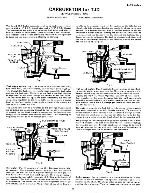
<strong>Th</strong>e Zenith 68-7 Series carburetor is of an up-draft single venturi<br />
design with a I" S.A.E. barrel size and a 7[8" S.A.E. flange.<br />
<strong>Th</strong>e carburetors are made with selective fuel inlet, and with or<br />
without a main jet adjustment. <strong>Th</strong>ese carburetors are =balanced"<br />
and "sealed", and the semi-concentric fuel bowl allows operation<br />
to quite extreme angles without flooding or starving.<br />
FUEL<br />
BOWL VENT<br />
needle in this passage controls the suction on the idle jet and<br />
thereby the idle mixture. Turning the needle in closer to its seat<br />
results in a greater suction with a smaller amount of air and<br />
therefore a richer mixture. Turning the needle out away from its<br />
seat increases the amount of air and reduces the suction, and a<br />
leaner mixture is delivered. <strong>Th</strong>e fuel is atomized and mixed with<br />
the air in the passage leading to the discharge holes and enters<br />
the air stream at this point.<br />
FUEL VALVE,<br />
SEAT<br />
FUEL VALVE<br />
NEEDLE<br />
WELL VENT<br />
VENTURI<br />
MAIN JET<br />
Fig. I<br />
Fuel supply system, Fig. 1, is made up of a threaded fuel inlet,<br />
(uel valve seat, fuel valve needle, float and fuel bowl. Fuel travels<br />
through the fuel valve seat and passes around the fuel val~e<br />
and into the fuel bowl. <strong>Th</strong>e level of the fuel in the fuel chamber<br />
is regulated by the float through its control of the fuel valve.<br />
<strong>Th</strong>e fuel valve does not open and close alternately but assumes<br />
an opening, regulated by the float, sufficient to maintain a proper<br />
level in the .fuel chamber equal to the demand of the engine according<br />
to its speed and load.<br />
<strong>Th</strong>e inside bowl vent as illustrated, by the passage originating in<br />
the air intake and continuing through to the fuel bowl, is a method<br />
of venting the fuel bowl to maintain proper air fuel mixtures even<br />
though the air cleaner may become restricted. <strong>Th</strong>is balancing is<br />
frequently ". referred to as an "inside bowl vent<br />
IDLE<br />
NEEDLE<br />
IDLE DISCHARGE HOLES<br />
E PLATE<br />
(Idle Position)<br />
Fig. 3<br />
High speed system, Fig. 3, controls the fuel mixture at part throttle<br />
speeds and at wide open throttle. <strong>Th</strong>is system consists of a<br />
venturi, controlling the maximum volume of air admitted into th<br />
engine; the main iet, which regulates the flow of fuel from t},<br />
float chamber to the main discharge jet; the well vent, which<br />
maintains uniform mixture ratio under changing suction and engine<br />
speeds; and a main discharge jet, which delivers the fuel<br />
into the air stream.<br />
<strong>Th</strong>e main jet controls the fuel delivery during part throttle range<br />
from about one-quarter to full throttle opening. To maintain a<br />
proper mixture, a small amount of air is admitted through the well<br />
vent into the discharge jet through air bleed holes in the discharge<br />
jet at a point below the level of fuel in the metering well.<br />
<strong>Th</strong>e passage of fuel through the high speed system is not a complicated<br />
process. <strong>Th</strong>e fuel flows from the fuel chamber thrbugh<br />
the main jet and into the main discharge jet where it is mixed<br />
with air admitted by the well vent, and the air-fuel mixture is<br />
then discharged into the air stream of the carburetor.<br />
IDLE AIR<br />
IDLE JET<br />
CHOKE<br />
(Open Position)<br />
IDLE FUEL<br />
PICK-UP<br />
PASSAGE<br />
Fig. 2<br />
Idle system, Fig. 2, consists of two idle discharge holes, idle<br />
air passage, idle adjusting needle, idle jet, and fuel pick-up<br />
passage. <strong>Th</strong>e fuel for idle is supplied through the main jet to a<br />
well directly below the main discharge jet. <strong>Th</strong>e pick-up passage<br />
is connected to this well by a restricted drilling at the bottom of<br />
this passage. <strong>Th</strong>e fuel travels through this channel to the idle<br />
jet calibration. <strong>Th</strong>e air for the idle mixture originates back of (or<br />
from behind) the main venturi. <strong>Th</strong>e position of the idle adjusting<br />
Fig. 4<br />
Choke system, Fig. 4, donsists of a valve mounted on a shaft<br />
located in the ai~ entrance and operated externally by a lever<br />
mounted on the shaft. <strong>Th</strong>e choke valve is used to restrict the air<br />
entering the carburetor. <strong>Th</strong>is increases the suction on the jets<br />
33