W2-880 Tjd, Thd, Th - Repair - Wisconsin Motors
W2-880 Tjd, Thd, Th - Repair - Wisconsin Motors
W2-880 Tjd, Thd, Th - Repair - Wisconsin Motors

You also want an ePaper? Increase the reach of your titles
YUMPU automatically turns print PDFs into web optimized ePapers that Google loves.
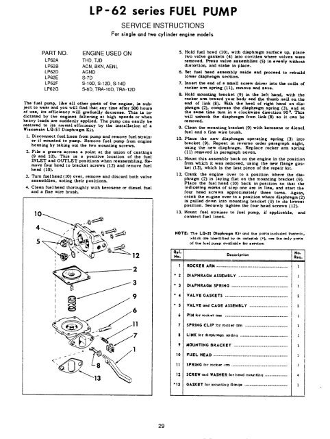
LP-62 series FUEL PUMP<br />
SERVICE INSTRUCTIONS<br />
For single and two cylinder engine models<br />
PART NO.<br />
LP62A<br />
LP62B<br />
LP62D<br />
LP62E<br />
LP62F<br />
LP62G<br />
ENGINE USED ON<br />
THD, TJD<br />
ACN, BKN, AENL<br />
AGND<br />
S-7D<br />
S-10D, S-12D, S-14D<br />
S-8D, TRA-10D, TRA-12D<br />
<strong>Th</strong>e fuel pump, like all other parts of the engine, is subject<br />
to w~ar and you will find t~at any time after 500 hours<br />
of use, its efficiency will gradually decrease. <strong>Th</strong>is is<br />
dictated by the engines faltering at high speeds or when<br />
heavy loads are suddenly applied. <strong>Th</strong>e pump can easily be<br />
restored to its normal efficiency by the installation of a<br />
<strong>Wisconsin</strong> LQ-5| Diaphragm Kit.<br />
1. Discormect fuel lines from pump and remove fuel strainer<br />
if mounted to pump. Remove fuel pump from engine<br />
housing by taking out the two mounting screws.<br />
2. File a groove across a point at the union of castings<br />
(9 and 10). <strong>Th</strong>is is a positive location of the fuel<br />
INLET and OUTLET positions when reassembling. Remove<br />
four head to bracket screws (12) and remove fuel<br />
head (10).<br />
3. Turn fuelhead(10) over, remove and discard both valve<br />
assemblies, noting their positions.<br />
4. Clean fuelhead thoroughly with kerosene or diesel fuel<br />
and a fine wire brush.<br />
10<br />
S. Hold fuel head (10), with diaphragm surface up, place<br />
two valve gaskets (4) into covities where valves were<br />
removed. Press valve assemblies (5) in evenly without<br />
distortion, and stake in place.<br />
6. Set fuel head assembly as/de and proceed to rebuild<br />
lower diaphragm section.<br />
7. Insert the end of a small screw driver into the coils of<br />
rocker arm spring (11), remove and save.<br />
8. Hold mounLing bracket (9) in the left hand, with the<br />
rocker an~ toward your body and the thumb nail on the<br />
end of link (8). With the heel of right hand on diaphragm<br />
(2), compress the diaphragm spring (3), and<br />
the san~ time turn in a clockwise direction 90 °. <strong>Th</strong>is<br />
will unhook the diaphragm from link (8) so it can<br />
removed.<br />
9. Clean *.he mounting bracket (9) with kerosene or diesel<br />
fuel and s fine wire brush.<br />
10. Pisce the new diaphragm operating spring (3) into<br />
bracket (9). Repeat in reverse order paragraph eight,<br />
using the new diaphragm. Replace rocker arm spr/ng<br />
(11) removed in paragraph seven.<br />
11. Mount this assembly back on the engine in the position<br />
from which it was removed, using the new flange gasket<br />
(13), which is the last piece of the repair kit.<br />
12. Crank the engine over to a position where the diaphragm<br />
(2) is laying flat on the mounting bracket (9).<br />
Place the fuel head (10) back in position so that the<br />
indicoting marks of step one are in line, and start the<br />
four head screws approximately three turns. Again,<br />
crank the m~gine over to a position where diaphragm (2)<br />
is pulled down into mounting bracket (9) to its lowest<br />
position. Securely tighten the four head screws (12).<br />
13. Mount fuel strainer to fuel pump, if applicable, and<br />
connect fuel lines.<br />
NOTE: <strong>Th</strong>e LQ-$1 Diaphragm Kit a~d the pc~ts included there-in,<br />
which a~e ldes~tfted by an ~teri~ (*), am the ~,.|y pa~s<br />
of the rue| pump a~a~lab|e Jot service.<br />
~<br />
2<br />
Ref.<br />
No.<br />
1 ROCKER ARM<br />
Description<br />
* 2 DIAPHRAGM ASSEMBLY ............................................<br />
* 3 DIAPHRAGM SPRING ..................................................<br />
* 4 VALVE GASKETS ........................................................<br />
* 5 VALVE and CAGE ASSEMBLY ..................................<br />
6 PIN ~or rocker azm ........................................................<br />
7 SPRING CLIP .~or rocker ann ......................................<br />
$ LINK ~or diaphrac~n sp~nq ..........................................<br />
9 MOUNTING BRACKET ................................................<br />
10 FUEL HEAD ..................................................................<br />
No.<br />
Req.<br />
I<br />
2<br />
2<br />
I<br />
I<br />
11 SPRING for ,’ocker ~rm ..................................................<br />
12 SCREW and WASHER for heczd mottnt~Lnq ....................<br />
"13 GASKET for mountlnq fl~qe ......................................<br />
I<br />
4<br />
29