W2-880 Tjd, Thd, Th - Repair - Wisconsin Motors
W2-880 Tjd, Thd, Th - Repair - Wisconsin Motors
W2-880 Tjd, Thd, Th - Repair - Wisconsin Motors

Create successful ePaper yourself
Turn your PDF publications into a flip-book with our unique Google optimized e-Paper software.
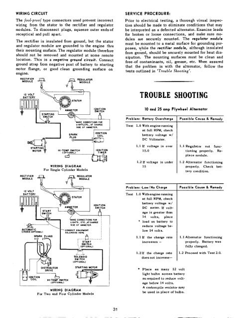
WIRING CIRCUIT<br />
<strong>Th</strong>e goal-proof type connectors used prevent incorrect<br />
wiring from the stator to the rectifier and regulator<br />
modules. To disconnect plugs, squeeze outer ends of<br />
receptical and pull apart.<br />
<strong>Th</strong>e rectifier is insulated from ground, but the stator<br />
and regulator module are grounded to the engine thru<br />
their mounting surface. <strong>Th</strong>e regulator module therefore<br />
should not be removed and mounted at some remote<br />
location. <strong>Th</strong>is is a negative ground circuit. Connect<br />
ground strap from negative post of battery to starting<br />
motor flange, or good clean grounding surface on<br />
engine.<br />
SERVICE PROCEDURE:<br />
Prior to electrical testing, a thorough visual inspection<br />
should be made to eliminate conditions that may<br />
be interpreted as a defected alternator. Examine leads<br />
for broken or loose connections, and make sure modules<br />
are securely mounted. <strong>Th</strong>e regulator module<br />
must be mounted to a metal surface for grounding purposes,<br />
while the rectifier module, although insulated<br />
from ground, should be securely mounted for heat dissipation.<br />
<strong>Th</strong>e mounting surfaces must be cIean and<br />
free.of contaminants, oil, grease, etc. When assured<br />
that the problem is with the alternator, follow the<br />
tests outlined in ’Trouble Shooting’.<br />
RECTIFIER ~ f---I REGULATOR<br />
12 VOLT ~ ~ ’ I<br />
BATTERY ~ ~<br />
TROUBLE SHOOTING<br />
v<br />
/ START, NG<br />
I I SWITCH ~|~<br />
10 and 25 amp Flywheel Alternator<br />
Problem: Battery Overcharge Possible Cause & Remedy<br />
Test 1.0 With engine running<br />
~<br />
SPARK ....<br />
_ I PLUG<br />
IGNITION<br />
at full RPM, check<br />
battery voltage w/<br />
DC Voltmeter.<br />
MOTOR ~<br />
HI-TEMP SW~TCH<br />
(OPTIORAL)<br />
IGNITION<br />
TIMER<br />
1.1 If voltage is over<br />
15.0<br />
1.1 Regulator not functioning<br />
properly. Replace<br />
module.<br />
WIRING DIAGRAM<br />
For Single Cylinder Models<br />
1.2 If voltage is under<br />
15<br />
1.2 Alternator functioning<br />
properly. Check battery<br />
condition.<br />
MODULE<br />
12 VOLT ~ ~ I I<br />
BATTERY ~ ~ STATOR I<br />
[~<br />
" = AMMETER ~MM~ETER J IGNITION<br />
SWITCH<br />
~--I~ I START L"<br />
AUTOMATIG<br />
CHOKE (OPTIONAL)<br />
SPARK PLUGS<br />
\1 L.G.TS, ETC.,ATCHAR6E :<br />
~60NNECT EOUIP~ENT ~<br />
SOLENOIDS HERE<br />
~ .... ~_~ ......<br />
’ START<br />
, SWITCH<br />
\ (OPTIONAL)<br />
Problem: "Low/No Charge Possible Cause & Remedy<br />
Te st 1.0 With engine running<br />
1.1<br />
at full RPM, check<br />
battery voltage w/<br />
DC meter. If voltage<br />
is greater than<br />
14 volts, place<br />
load on battery to<br />
reduce voltage below<br />
14 volts.<br />
If the charge rate<br />
increases --<br />
1.1 Alternator functioning<br />
properly. Battery was<br />
fully<br />
charged.<br />
SOLENOID<br />
SWITCH<br />
1.2If the charge rate<br />
does<br />
not increase--<br />
1.2 Proceed with Test 2.0.<br />
DISTRIBUTOR<br />
DRIVE<br />
IGNITION ~<br />
COIL HI-TEMP SWITCH<br />
(OPTIONAL)<br />
STARTING MOTOR<br />
WlRIN .G DIAGRAM<br />
For Two and Four Cylinder Models<br />
* Place as many 12 volt<br />
light bulbs across battery<br />
as required to reduce voltage<br />
below 14 volts.<br />
A carbonpile resistor may<br />
be used in place<br />
of bulbs.<br />
31