W2-880 Tjd, Thd, Th - Repair - Wisconsin Motors
W2-880 Tjd, Thd, Th - Repair - Wisconsin Motors
W2-880 Tjd, Thd, Th - Repair - Wisconsin Motors

Create successful ePaper yourself
Turn your PDF publications into a flip-book with our unique Google optimized e-Paper software.
compression will be weak, <strong>Th</strong>is may cause difficulty in starting.<br />
To remedy this condition, remove the spark plugs and pour<br />
about a fluid ounce of crankcase oil through the spark plug hole<br />
into each cylinder.<br />
Turn the engine over several times with the st,qa’ting crank to<br />
distribute the oil over the cylindtr wall. <strong>Th</strong>en reassemble spark<br />
plugs and compression should be satisfactory.<br />
OPERATION<br />
GOVERNOR<br />
<strong>Th</strong>e centrifugal flyball governor rotates on a stationary pin<br />
driven into the upper part of the timing gear cover, and the<br />
governor is driven off the camshaft gear at crankshaft speed.<br />
"ONTROL<br />
GOVERNOR<br />
GOV<br />
CARBURLTOR<br />
THROTTLE LEVER<br />
Flyweights are hinged to lugs on the drive gear. Hardened pins<br />
on the flyweights bear against the flanged sliding sleeve,<br />
moving it back and forth as the flyweights move in or out. <strong>Th</strong>e<br />
motion of the sleeve is transmitted through a ball thrust beating<br />
to the governor lever, which in tum is connected to the carburetor<br />
throttle lever. A spring connected to the governor lever tends<br />
to hold the flyweights to their inner position, also to hold the<br />
carburetor throttle open. As the engine speed increases, cen-<br />
Irifugal force from the flyweights acts against ~he spring and<br />
closes the throttle to a point where the engine speed will be<br />
maintained practically constant under varying load conditions.<br />
GOVERNOR ADJUSTMENT (Fig. 23,Fig. 23A, Fig. 24,<br />
Fig. 24A)<br />
<strong>Th</strong>e governor rod connection to the carburetor must be very<br />
carefully adjusted for length, otherwise the governor will not<br />
function properly and cause the engine to surge badly. With the<br />
engine at rest, the governor spring will keep the flyweights in,<br />
and the control rod must be of such length as to hold the<br />
carburetor throttle wide open at that point.<br />
CONTROL ROD<br />
<strong>W2</strong>-<strong>880</strong>, TJD, THD, TH- With die control rod discon:nec[cd from [he<br />
governor liver, push the rod toward the carburetor as far as it will<br />
go. <strong>Th</strong>is will put the carburetor throttle leverin a wide open<br />
position. <strong>Th</strong>e govemor lever should then be<br />
moved as far as possible in the same direction.<br />
Holding both parts in the above position, the THROTTLE<br />
rod should be screwed in or out of the swivel LEVER<br />
blockon the carburetor, until the bent end of<br />
the rod will register with hole in lever, then<br />
POSITION<br />
screw rod in one more turn. <strong>Th</strong>e extra turn will<br />
STOP<br />
shorten the linkage slightly and will enable the<br />
carburetor throttle lever to bounce back from<br />
the stop pin rather that jam against the pin,<br />
when a load is suddenly applied to an idling<br />
engine. <strong>Th</strong>is will eliminate excessive wear on<br />
the threads in the carburetor throttle swivel<br />
block.<br />
<strong>W2</strong>-<strong>880</strong> - Remove retaining clip and disconnect<br />
the control rod from the carburetor<br />
throttle lever (Fig. 23A). Move the top of the<br />
govemor lever toward the lake off end of the<br />
engine. Hold the carburetor throttle lever in<br />
the wide open position against the carburetor<br />
stop. Adjust length of control rod so rod will<br />
register in hole in carburetor throttle lever,<br />
then lengthen rod one full turn so carburetor<br />
throttle lever will stop just short of wide open<br />
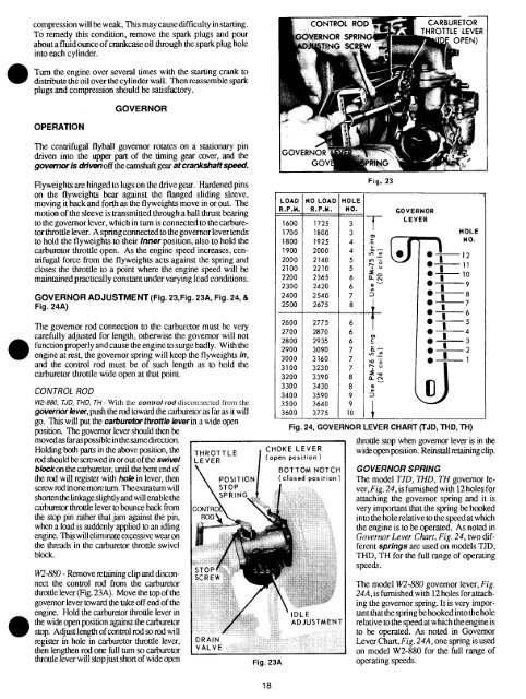
LOAD NO LOAD HOLE<br />
R.P.M. R.P.M. NO.<br />
1600 1725 3<br />
1700 1800 3<br />
1800 1925 4<br />
1900 2000 4<br />
2000 2140 5<br />
2100 2210 5<br />
2200 2365 6<br />
2300 2420 6<br />
2400 2540 7<br />
2500 2675 8<br />
2600 2775 6<br />
2700 2870 6<br />
2800 2935 6<br />
2900 3090 3000 3160 7<br />
3100 3230 7<br />
3200 3390 8<br />
3300 3430 8<br />
3400 3590 9<br />
3500 3640 9<br />
3600 3775 10<br />
CHOKE LEVER<br />
(open position)<br />
Fig. 23A<br />
18<br />
BOTTOM NOTCH<br />
(closed position)<br />
ADJUSTMENT<br />
Fig. 23<br />
GOVERNOR<br />
LEVER<br />
HOLE<br />
¯ --7<br />
O~6<br />
O-- 5<br />
0----4<br />
0~3<br />
¯ -- ~-- 2<br />
Fig. 24, GOVERNOR LEVER CHART (TJD, THD, TH)<br />
throttle stop when govemor lever is in the<br />
wide open position. Reinstall retaining clip.<br />
GOVERNOR SPRING<br />
<strong>Th</strong>e model TJD, THD, TH governor lever,<br />
Fig. 24, is furnished with 12 holes for<br />
attaching the governor spring and it is<br />
very important that the spring be hooked<br />
into the hole relative to the speed at which<br />
the engine is to be operated. As noted in<br />
Governor Lever Chart, Fig. 24, two different<br />
springs are used on models TJD,<br />
THD, TH for the full range of operating<br />
speeds.<br />
<strong>Th</strong>e model <strong>W2</strong>-<strong>880</strong> governor lever, Fig.<br />
24A, is furnished with 12 holes for attaching<br />
the governor spring. It is very important<br />
that the spring be hooked into the hole<br />
relative to the speed at which the engine is<br />
to be operated. As noted in Governor<br />
Lever Chart, Fig. 24A, one spring is used<br />
on model <strong>W2</strong>-<strong>880</strong> for the full range of<br />
operating speeds.