W2-880 Tjd, Thd, Th - Repair - Wisconsin Motors
W2-880 Tjd, Thd, Th - Repair - Wisconsin Motors
W2-880 Tjd, Thd, Th - Repair - Wisconsin Motors

Create successful ePaper yourself
Turn your PDF publications into a flip-book with our unique Google optimized e-Paper software.
WICO MODEL XH-2D MAGNETO<br />
Y-67 Series<br />
WlCO No. XH-1961C (Replaces XH-1961), WlS. No. Y-67, For MODELS TE and TF ENGINE<br />
WlCO No. XH-2531C (Replaces XH-2531 and XH-1961C), WlS. No. Y-67-A, For MODELS TE, TF, TH ENGINE<br />
SERVICE<br />
INSTRUCTIONS<br />
41 32 50<br />
51 28<br />
36" 5<br />
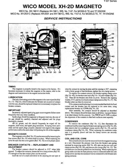
TIMING<br />
<strong>Th</strong>e magneto is properly timed to the engine at the factory. If it<br />
becomes necessary to retime the magneto to the engine, refer to the<br />
diagram and instructions in the engine instruction book.<br />
LUBRICATION<br />
<strong>Th</strong>e only lubricating pointin themagneto is the cam wiper felt (Ref.<br />
No. 17). TbJs felt, which lubricates the breaker arm at point of contact<br />
with the cam, should be replaced whenever it is necessary to replace the<br />
breaker contacts.<br />
IMPORTANT<br />
Incorrectly adjusted spark plug gaps cause magneto failure more<br />
frequendy than any other condition.<br />
Spark plugs should be inspected at frequent intervals, the size of<br />
the gap should be carefully checked and adjusted and the plugs<br />
thoroughly cleaned.<br />
All oil, grease, and dirt should frequently be wiped off the<br />
magneto, lead wires, and spark plug insulators. Keeping these parts<br />
clean and the spark plugs properly adjusted will improve the engine<br />
performance and at the same time will prolong the life of the magneto.<br />
MAGNETO COVER<br />
<strong>Th</strong>e magneto cover (Ref. No. 53) can beremoved by loosening the<br />
four screws (Ref. No. 33) which hold it in place. When replacing the<br />
cover be sure that the cover gasket (Ref. No. 32) is in its proper place.<br />
BREAKER CONTACTS -- REPLACEMENT AND<br />
ADJUSTMENT<br />
<strong>Th</strong>e breaker contacts should be adjusted to .015" when fully<br />
opened. To adjust the contacts, loosen the two clamp screws (Ref. No.<br />
37) enough so that the contact plate can be moved.<br />
Insert the end of a small screwdriver in flae adjusting slot and open or<br />
close the contacts by moving the plate until the opening is .015", treasuring<br />
with a feeler gauge of that thickness, tighten the two clamp screws.<br />
To replace the contacts remove the breaker spring clamp screw<br />
(Ref No. 40), the breaker arm lock (Ref No. 16) and washer (Ref<br />
12). <strong>Th</strong>en lift the breaker arm from its pivot. Remove the aligning<br />
washer,5717,andthetwofixedcontactclampscrews(RefNo.37). <strong>Th</strong>e<br />
breaker plate can then be removed.<br />
If the contacts need replacing i t is recommended that both the fixed<br />
contact and the breaker arm be replaced at the same time, using<br />
replacement breaker set X5996 (Ref No. 39).<br />
After assembly, the contacts should be adjusted as described<br />
above. <strong>Th</strong>e contacts should be kept clean at all times. Lacquer thinner<br />
is an ideal cleaner for this purpose. Use WICO tool S-5449, to adjust<br />
the alignment of the contacts so that both surfaces meet squarely.<br />
CONDENSER<br />
To remove the condenser (Ref. No. 31), first disconnect the<br />
condenser lead byremoving the breaker arm spring screw (Ref. No. 40),<br />
then remove the two condenser clamp screws (Ref. No. 19), and the<br />
condenser clamp (Ref. No. 28). When replacing the condenser make<br />
sure it is properly placed and that the clamp screws are securely<br />
tightened.<br />
COIL AND COIL CORE<br />
<strong>Th</strong>e coil and coil core must be removed from the magneto housing<br />
as a unit. Disconnect the primary wire from the breaker arm spring<br />
terminal by removing screw (Ref No. 40), take out the two coil core<br />
clamp screws (R ef No. 20), and remove the clamps (Ref No. 35). <strong>Th</strong>e<br />
coil and core can then be pulled from the housing. When replacing this<br />
group make sure that the bare primary wire is connected under the core<br />
clamp screw and that the insulated wire is connected to the breaker arm<br />
spring terminal.<br />
41