SPICE-Simulation using LTspice IV
SPICE-Simulation using LTspice IV
SPICE-Simulation using LTspice IV

You also want an ePaper? Increase the reach of your titles
YUMPU automatically turns print PDFs into web optimized ePapers that Google loves.
6.2. Important: creating <strong>SPICE</strong> Model and Symbol for a Transformer<br />
6.2.1. The easiest Solution: a simple ideal Transformer<br />
Sorry, but in the LTSpice part library you can’t find any transformer! So let us start with a simple but good solution<br />
found in the original <strong>SPICE</strong> manual:<br />
Place the necessary windings (with their Inductances) in the schematic and add a <strong>SPICE</strong> Directive for the<br />
magnetic coupling “kn” between these windings!<br />
Example for a two winding transformer and voltage transfer ratio<br />
= 1:1<br />
a) Place “Ind2” from the symbol library two times on the screen,<br />
because only at this symbol the start of the winding procedure is<br />
marked by a circle.<br />
b) The line “k1 L1 L2 1” says that the magnetic coupling factor<br />
between the windings L1 and L2 is “1” = 100%.<br />
c) Attention: It is not possible to enter a given voltage transfer ratio “(N1 / N2)” into<br />
P<strong>SPICE</strong>!!<br />
The reason is not complicated: P<strong>SPICE</strong> works always and only with parts and their properties (here: inductances<br />
and magnetic coupling factor). So we must use the inductances and the following relation:<br />
L<br />
L<br />
Primary<br />
Secondary<br />
N1<br />
= <br />
N2 <br />
2<br />
So choose a realistic value for L1 and then calculate L2 by <strong>using</strong> this formula.<br />
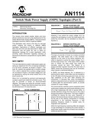
6.2.2. Creation of the <strong>SPICE</strong> Model for a real Two Windings Transformer<br />
We use the following transformer model for our work, which includes the „magnetic coupling“ between the primary<br />
and secondary winding, the flux leakage inductances, the winding capacitances and the copper resistors of the<br />
windings.<br />
Node 1 and 2 are the<br />
primary winding<br />
connections, node 3<br />
and 4 the connections<br />
for the secondary<br />
winding of the model<br />
for the simulation.<br />
For the “inner nodes”<br />
you should choose<br />
much higher numbers<br />
to avoid collisions<br />
when “blowing up the<br />
circuit diagram” with<br />
more windings ore<br />
parts.<br />
35