SPICE-Simulation using LTspice IV
SPICE-Simulation using LTspice IV
SPICE-Simulation using LTspice IV

You also want an ePaper? Increase the reach of your titles
YUMPU automatically turns print PDFs into web optimized ePapers that Google loves.
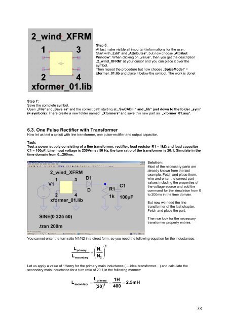
Step 6:<br />
At last make visible all important informations for the user.<br />
Start with „Edit“ and „Attributes“, but now choose „Attribut<br />
Window“. When clicking on „value“, then you get the description<br />
„2_wind_XFRM“ at your cursor and you can place it over the<br />
symbol.<br />
Then repeat the procedure but now choose „SpiceModel“ =<br />
xformer_01.lib and place it below the symbol. The work is done!<br />
Step 7:<br />
Save the complete symbol.<br />
Open „File“ and „Save as“ and the correct path starting at „SwCADIII“ and „lib“ just down to the folder „sym“<br />
(= symbols). There create a new folder named „Xformers“ and save this new part as „xformer_01.asy“.<br />
6.3. One Pulse Rectifier with Transformer<br />
Now let us test a circuit with line transformer, one pulse-rectifier and output capacitor.<br />
Task:<br />
Test a power supply consisting of a line transformer, rectifier, load resistor R1 = 1k and load capacitor<br />
C1 = 100µF. Line input voltage is 230Vrms / 50 Hz, the turn ratio of the transformer is 20:1. Simulate in the<br />
time domain from 0...200ms.<br />
Solution:<br />
Most of the necessary parts are<br />
already known from the last<br />
example. Fetch and place them,<br />
wire and enter the correct part<br />
values including the properties of<br />
the voltage source and add the<br />
command for the simulation from 0<br />
to 200ms in the time domain.<br />
But now we need the line<br />
transformer of the last chapter.<br />
Fetch and place the part.<br />
Then we look for the necessary<br />
transformer property entries.<br />
You cannot enter the turn ratio N1/N2 in a direct form, so you need the following equation for the inductances:<br />
L<br />
L<br />
primary<br />
secondary<br />
N<br />
=<br />
<br />
N<br />
1<br />
2<br />
<br />
<br />
<br />
2<br />
Let us apply a value of 1Henry for the primary main inductance (….ideal transformer…) and calculate the<br />
secondary main inductance for a turn ratio of 20:1 in the following manner:<br />
L<br />
=<br />
( 20)<br />
1H<br />
=<br />
400<br />
primary<br />
L<br />
secondary<br />
=<br />
2<br />
2.5mH<br />
38