August 2011 - Haas Automation, Inc.
August 2011 - Haas Automation, Inc.
August 2011 - Haas Automation, Inc.

You also want an ePaper? Increase the reach of your titles
YUMPU automatically turns print PDFs into web optimized ePapers that Google loves.
ON<br />
CYCLE<br />
START<br />
SERVO<br />
ON<br />
CYCLE<br />
START<br />
0 9<br />
EMERGENCY<br />
STOP<br />
0<br />
HIGH<br />
LOAD LOAD<br />
9<br />
RETURN<br />
MODE PROG<br />
SCAN<br />
CLEAR<br />
JOG<br />
ZERO<br />
RETURN<br />
4 5 6<br />
1 2 3<br />
0<br />
CLEAR<br />
ZERO<br />
SET<br />
MODE<br />
RUN<br />
PROG<br />
DISPLAY<br />
SCAN<br />
STEP<br />
SCAN<br />
7<br />
4<br />
1<br />
5<br />
ZERO<br />
SET<br />
2<br />
6<br />
3<br />
DISPLAY<br />
STEP<br />
SCAN<br />
MADE IN U.S.A.<br />
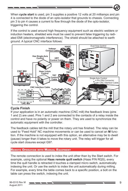
When cycle start is used, pin 3 supplies a positive 12 volts at 20 milliamps and pin<br />
4 is connected to the diode of an opto-isolator that grounds to chassis. Connecting<br />
pin 3 to pin 4 causes a current to flow through the diode of the opto-isolator,<br />
triggering the control.<br />
If the control is used around high frequency equipment such as electric welders or<br />
induction heaters, shielded wire must be used to prevent false triggering by radiated<br />
EMI (electromagnetic interference). The shield should be attached to earth<br />
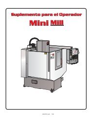
ground. A typical CNC interface follows:<br />
Indexer<br />
Control Cable<br />
HA5C<br />
AUTOMATION<br />
Dual Axis Control<br />
Haa Single-Axis<br />
Control<br />
HRT<br />
Control Cable<br />
HRT<br />
POWER STEP DEGR ES<br />
RU NING OVER<br />
CNC Mill<br />
RS-232<br />
- +<br />
JOG ZERO<br />
8 9 RUN<br />
0 -<br />
<strong>Haas</strong> 2-Axis<br />
Control<br />
Brushle s<br />
Rotary Two-Axis<br />
Control<br />
EMERGENCY STOP<br />
7 8 9<br />
TRT<br />
Control<br />
Cable<br />
TRT<br />
Single Axis Control<br />
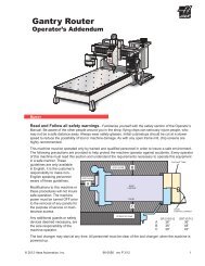
4 Pin DIN Connector<br />
with CNC Interface Cable<br />
M Function<br />
Relay<br />
+24 Volts<br />
M FIN Signal<br />
CNC Mill<br />
CNC Interface Cable<br />
4 Pin Din Connector<br />
Rear of Controller<br />
680 OHM<br />
3<br />
4<br />
2<br />
1<br />
CYCLE<br />
START<br />
+12 Volts<br />
CYCLE<br />
FINISH<br />
<strong>Haas</strong> TRT Internal<br />
Cycle Finish<br />
If your application is in an automatic machine (CNC mill) the feedback lines (pins<br />
1 and 2) are used. Pins 1 and 2 are connected to the contacts of a relay inside the<br />
control and have no polarity or power on them. They are used to synchronize the<br />
automatic equipment with the controller.<br />
The feedback cables tell the mill that the rotary unit has finished. The relay can be<br />
used to “Feed Hold” NC machine movements or can be used to cancel an M function.<br />
If the machine is not equipped with this option, an alternative may be to dwell<br />
(pause) longer than it takes to move the rotary unit. The relay will trigger for all<br />
cycle start closures except G97.<br />
Remote Operation with Manual Equipment<br />
The remote connection is used to index the unit other than by the Start switch. For<br />
example, using the optional <strong>Haas</strong> remote quill switch (<strong>Haas</strong> P/N RQS), every<br />
time the quill handle is retracted it touches a clamped micro switch, automatically<br />
indexing the unit. Or use the switch to index the unit automatically during milling.<br />
For example, every time the table comes back to a specific position, a bolt on the<br />
table can press the switch, indexing the unit.<br />
96-0315 Rev M<br />
<strong>August</strong> <strong>2011</strong><br />
9