August 2011 - Haas Automation, Inc.
August 2011 - Haas Automation, Inc.
August 2011 - Haas Automation, Inc.
You also want an ePaper? Increase the reach of your titles
YUMPU automatically turns print PDFs into web optimized ePapers that Google loves.
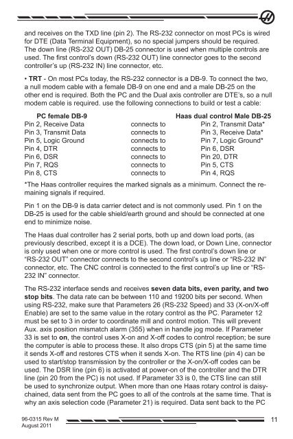
and receives on the TXD line (pin 2). The RS-232 connector on most PCs is wired<br />
for DTE (Data Terminal Equipment), so no special jumpers should be required.<br />
The down line (RS-232 OUT) DB-25 connector is used when multiple controls are<br />
used. The first control’s down (RS-232 OUT) line connector goes to the second<br />
controller’s up (RS-232 IN) line connector, etc.<br />
• TRT - On most PCs today, the RS-232 connector is a DB-9. To connect the two,<br />
a null modem cable with a female DB-9 on one end and a male DB-25 on the<br />
other end is required. Both the PC and the Dual axis controller are DTE’s, so a null<br />
modem cable is required. use the following connections to build or test a cable:<br />
PC female DB-9<br />
<strong>Haas</strong> dual control Male DB-25<br />
Pin 2, Receive Data connects to Pin 2, Transmit Data*<br />
Pin 3, Transmit Data connects to Pin 3, Receive Data*<br />
Pin 5, Logic Ground connects to Pin 7, Logic Ground*<br />
Pin 4, DTR connects to Pin 6, DSR<br />
Pin 6, DSR connects to Pin 20, DTR<br />
Pin 7, RQS connects to Pin 5, CTS<br />
Pin 8, CTS connects to Pin 4, RQS<br />
*The <strong>Haas</strong> controller requires the marked signals as a minimum. Connect the remaining<br />
signals if required.<br />
Pin 1 on the DB-9 is data carrier detect and is not commonly used. Pin 1 on the<br />
DB-25 is used for the cable shield/earth ground and should be connected at one<br />
end to minimize noise.<br />
The <strong>Haas</strong> dual controller has 2 serial ports, both up and down load ports, (as<br />
previously described, except it is a DCE). The down load, or Down Line, connector<br />
is only used when one or more control is used. The first control’s down line or<br />
“RS-232 OUT” connector connects to the second control’s up line or “RS-232 IN”<br />
connector, etc. The CNC control is connected to the first control’s up line or “RS-<br />
232 IN” connector.<br />
The RS-232 interface sends and receives seven data bits, even parity, and two<br />
stop bits. The data rate can be between 110 and 19200 bits per second. When<br />
using RS-232, make sure that Parameters 26 (RS-232 Speed) and 33 (X-on/X-off<br />
Enable) are set to the same value in the rotary control as the PC. Parameter 12<br />
must be set to 3 in order to coordinate mill and control motion. This will prevent<br />
Aux. axis position mismatch alarm (355) when in handle jog mode. If Parameter<br />
33 is set to on, the control uses X-on and X-off codes to control reception; be sure<br />
the computer is able to process these. It also drops CTS (pin 5) at the same time<br />
it sends X-off and restores CTS when it sends X-on. The RTS line (pin 4) can be<br />
used to start/stop transmission by the controller or the X-on/X-off codes can be<br />
used. The DSR line (pin 6) is activated at power-on of the controller and the DTR<br />
line (pin 20 from the PC) is not used. If Parameter 33 is 0, the CTS line can still<br />
be used to synchronize output. When more than one <strong>Haas</strong> rotary control is daisychained,<br />
data sent from the PC goes to all of the controls at the same time. That is<br />
why an axis selection code (Parameter 21) is required. Data sent back to the PC<br />
96-0315 Rev M<br />
<strong>August</strong> <strong>2011</strong><br />
11


