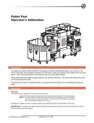
August 2011 - Haas Automation, Inc.
August 2011 - Haas Automation, Inc.
August 2011 - Haas Automation, Inc.

You also want an ePaper? Increase the reach of your titles
YUMPU automatically turns print PDFs into web optimized ePapers that Google loves.
elease the collet. If, after repeated use, the spring will not push the collet out, use<br />
one of the following methods to remove the collet and lubricate the outside of the<br />
collet with a light grease before re-inserting:<br />
1. If the three-way air valve becomes clogged, exhaust airflow may be<br />
restricted, causing the collet to stick in the taper. Leave the valve clamped,<br />
and connect and disconnect the air supply several times.<br />
2. If the above procedure does not free the collet, switch the valve to the<br />
unclamped position, then gently tap the back end of the drawtube with a<br />
plastic-faced mallet.<br />
HA5C Tooling Locations<br />
The HA5C is equipped with tooling points in order to speed setups. One of the<br />
most time-consuming procedures in setup is aligning the head with the table. On<br />
the mounting surfaces are two 0.500” bored holes on 3.000” centers. The holes on<br />
the bottom surface are parallel to the spindle within 0.0005” per 6 inches and on<br />
center within ±0.001”. By boring matching holes in the tooling plate, setups become<br />
routine. Using tooling holes will also prevent the head from shifting on the mill table<br />
when the part is subjected to heavy cutting forces.<br />
On CNC mills, a machined stepped plug of 0.500” diameter one side and 0.625” on<br />
the other comes with the <strong>Haas</strong> head. The 0.625” diameter fits into the T-slot of the<br />
mill table. This will give quick parallel alignment.<br />
Dual Axes Coordinate System<br />
The layout of the A and B axes of the <strong>Haas</strong> five-axis control are shown in the<br />
following figures. The A-axis is rotary motion about the X-axis, while the B-axis<br />
determines rotary motion about the Y-axis. The right hand rule can be used to<br />
determine axis rotation for the A and B axes. When placing the thumb of the right<br />
hand along the positive X-axis, the fingers of the right hand will point in the direction<br />
of tool movement for a positive A-axis command. Likewise, when placing the thumb<br />
of the right hand along the positive Y-axis, the fingers of the right hand will point<br />
in the direction of tool movement for a positive B-axis command. It is important to<br />
remember that the right hand rule determines direction of tool movement and not<br />
the table movement direction. For the right hand rule, the fingers will point opposite<br />
of the positive rotary table movement. Refer to the following figures.<br />
96-0315 Rev M<br />
<strong>August</strong> <strong>2011</strong><br />
23