

The Microcontroller Idea Book - Jan Axelson's Lakeview Research
The Microcontroller Idea Book - Jan Axelson's Lakeview Research
The Microcontroller Idea Book - Jan Axelson's Lakeview Research

Create successful ePaper yourself
Turn your PDF publications into a flip-book with our unique Google optimized e-Paper software.
Displays<br />
Interfacing<br />
Full control of an LCD module requires 8 bidirectional lines for reading and writing data<br />
and 3 outputs for the control signals. To save four lines, you can use the 4-bit data interface<br />
described later. Also, the ability to read the display and the busy flag at D7 are optional. If<br />
you give these up, you can use outputs (such as the 74HC374’s) instead of bidirectional port<br />
bits for D0-D7, and eliminate one of the control lines by tying R/W low.<br />
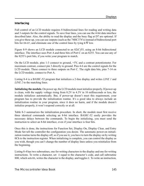
Figure 8-9 shows an LCD module connected to an 82(C)55, using an 8-bit bidirectional<br />
interface. <strong>The</strong> interface uses Port A and three bits of Port C on an 8255. You can use any of<br />
the 8255’s port bits, if you write your program to match.<br />
On the LCD module, pins 1-3 connect to ground, +5V, and a contrast potentiometer. For<br />
maximum contrast, connect pin 3 directly to ground. Pins 4-6 are the control signals for the<br />
LCD module. <strong>The</strong>se connect to three outputs on Port C. <strong>The</strong> eight data bits, pins 7-14 on<br />
the LCD module, connect to Port A.<br />
Listing 8-4 is a BASIC-52 program that initializes a 2-line display and writes LINE 1 and<br />
LINE 2 to the matching lines.<br />
Initializing the module. On power up, the LCD module must initialize properly. If power-up<br />
is clean, with the supply voltage rising from 0.2V to 4.5V in 10 milliseconds or less, the<br />
module initializes automatically. But, if power-up doesn’t meet this requirement, your<br />
program has to provide the initialization routine. It’s a good idea to always include an<br />
initialization routine in your program, since it does no harm, and if the module doesn’t<br />
initialize properly, it won’t respond correctly or at all.<br />
Table 8-3 summarizes the initialization procedure. In short, the module must first receive<br />
three identical commands selecting an 8-bit interface. BASIC-52 easily provides the<br />
necessary delays between the commands. To begin the initializing, you must send the<br />
instruction to select an 8-bit interface, even if your interface is four bits.<br />
Once this is done, the instructions for Function Set, Display On, Display Clear, and Entry<br />
Mode Set tell the controller the configuration you desire. <strong>The</strong> automatic power-on initialization<br />
routine turns the display off, so if you use it, you have to turn the display on by writing<br />
0Ch to the instruction register. When initializing is complete, you can control the display as<br />
you wish, though you can’t change the number of display lines unless you reinitialize from<br />
the beginning.<br />
Listing 8-4 has two subroutines, one for writing characters to the display and one for writing<br />
instructions. To write a character, set D equal to the character’s code, and call subroutine<br />
800, which sets RS, writes the character to the display, and toggles E. To write an instruction,<br />
<strong>The</strong> <strong>Microcontroller</strong> <strong>Idea</strong> <strong>Book</strong> 145


