- Page 1 and 2: The Microcontroller Idea Book Circu
- Page 3 and 4: Table of Contents Chapter 1 Microco
- Page 5 and 6: Chapter 11 Control Circuits 185 Swi
- Page 7 and 8: Introduction Introduction This book
- Page 9 and 10: A chapter on assembly-language inte
- Page 11 and 12: Microcontroller Basics 1 Microcontr
- Page 13 and 14: But along with cheap, powerful, and
- Page 15 and 16: makes sense. For simpler designs, a
- Page 17 and 18: Microcontroller Basics Several tech
- Page 19 and 20: Interpreters and compilers are two
- Page 21 and 22: Inside the 8052-BASIC 2 Inside the
- Page 23 and 24: Inside the 8052-BASIC • You can a
- Page 25 and 26: hardware manuals. For programming,
- Page 27 and 28: Inside the 8052-BASIC Figure 2-2 Pi
- Page 29 and 30: Inside the 8052-BASIC Table 2-2. (p
- Page 31 and 32: Inside the 8052-BASIC Code and data
- Page 33 and 34: Powering Up 3 Powering Up This chap
- Page 35 and 36: Powering Up Table 3-1. Parts list f
- Page 37 and 38: Powering Up Figure 3-2. Truth table
- Page 39 and 40: Powering Up Jumper J3 chooses the c
- Page 41 and 42: Powering Up Figure 3-3. This is the
- Page 43 and 44: Powering Up Construction Tips These
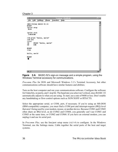
- Page 45: Powering Up Serial Connectors Conne
- Page 49 and 50: Powering Up PRINT XTAL Line Editing
- Page 51 and 52: Powering Up PORT 1 Bit Values: Bit
- Page 53 and 54: Powering Up Listing 3-3. Allows use
- Page 55 and 56: 10 CLOCK 1:TIME=0:SEC=0 20 A=0 30 P
- Page 57 and 58: Saving Programs 4 Saving Programs I
- Page 59 and 60: guaranteed for at least ten years.
- Page 61 and 62: Saving Programs Figure 4-3. Circuit
- Page 63 and 64: Jumper J4 is optional. It enables y
- Page 65 and 66: memory on bootup. This is what allo
- Page 67 and 68: This is the recommended algorithm f
- Page 69 and 70: Saving Programs Figure 4-5. Additio
- Page 71 and 72: problems with EPROMs that have a 10
- Page 73 and 74: supply. The chip requires an additi
- Page 75 and 76: Programming 5 Programming When you
- Page 77 and 78: Subroutines have two advantages. Fi
- Page 79 and 80: Programming • Hexadecimal numbers
- Page 81 and 82: Programming It can be hard to find
- Page 83 and 84: Programming Math Operators = + - *
- Page 85 and 86: Programming expression / expression
- Page 87 and 88: Programming DO: [program statements
- Page 89 and 90: Programming LOG(expression) Returns
- Page 91 and 92: Programming PH0.@ Same as PRINT@, b
- Page 93 and 94: Programming RCAP2 Retrieves or assi
- Page 95 and 96: Programming PRINT TAB(2) “hello
- Page 97 and 98:
Inputs and Outputs 6 Inputs and Out
- Page 99 and 100:
Unassigned space remains in the mem
- Page 101 and 102:
U11 is a 74HCT138 3-to-8-line decod
- Page 103 and 104:
If you wish, you can wire U14’s i
- Page 105 and 106:
Inputs and Outputs Figure 6-4. Outp
- Page 107 and 108:
Inputs and Outputs Listing 6-2. Set
- Page 109 and 110:
The 82C55 also has CMOS-compatible
- Page 111 and 112:
Inputs and Outputs Pin Symbol Input
- Page 113 and 114:
Inputs and Outputs An 8255 Interfac
- Page 115 and 116:
Inputs and Outputs XBY(0FC03h)=9BH
- Page 117 and 118:
To set or clear a different bit, de
- Page 119 and 120:
Switches and Keypads 7 Switches and
- Page 121 and 122:
Switches and Keypads Figure 7-2. Us
- Page 123 and 124:
exact value depending on the switch
- Page 125 and 126:
Switches and Keypads Figure 7-4. Tw
- Page 127 and 128:
Switches and Keypads Figure 7-6. A
- Page 129 and 130:
Switches and Keypads Custom Keypads
- Page 131 and 132:
Switches and Keypads • A single c
- Page 133 and 134:
Switches and Keypads Listing 7-3. T
- Page 135 and 136:
Displays 8 Displays In addition to
- Page 137 and 138:
Displays Figure 8-1. LED interfaces
- Page 139 and 140:
Displays Figure 8-2. Ways to connec
- Page 141 and 142:
Displays Figure 8-4. Four output po
- Page 143 and 144:
Displays Figure 8-5. The ICM7218D c
- Page 145 and 146:
In Figure 8-5’s circuit, an 82(C)
- Page 147 and 148:
Displays Figure 8-7. With the TC721
- Page 149 and 150:
Displays Figure 8-8. With a charact
- Page 151 and 152:
Table 8-1. LCD modules containing t
- Page 153 and 154:
Each character in the CG ROM and CG
- Page 155 and 156:
Displays Interfacing Full control o
- Page 157 and 158:
Displays Listing 8-4 (page 2 0f 2).
- Page 159 and 160:
Displays Listing 8-5. Displays key
- Page 161 and 162:
Displays Listing 8-6 (page 2 of 2).
- Page 163 and 164:
Using Sensors to Detect and Measure
- Page 165 and 166:
• What power supplies are availab
- Page 167 and 168:
Using Sensors to Detect and Measure
- Page 169 and 170:
Using Sensors to Detect and Measure
- Page 171 and 172:
different ground symbols for the tw
- Page 173 and 174:
10 REM use single-ended mode 20 REM
- Page 175 and 176:
Using Sensors to Detect and Measure
- Page 177 and 178:
Using Sensors to Detect and Measure
- Page 179 and 180:
Using Sensors to Detect and Measure
- Page 181 and 182:
Clocks and Calendars 10 Clocks and
- Page 183 and 184:
Listing 10-1. Uses BASIC-52’s rea
- Page 185 and 186:
Clocks and Calendars Figure 10-1. P
- Page 187 and 188:
Clocks and Calendars Table 10-1. Re
- Page 189 and 190:
If you want an alarm frequency othe
- Page 191 and 192:
Clocks and Calendars Listing 10-3 (
- Page 193 and 194:
Clocks and Calendars Listing 10-3 (
- Page 195 and 196:
Control Circuits 11 Control Circuit
- Page 197 and 198:
the LSTTL part, and wire the desire
- Page 199 and 200:
Control Circuits Listing 11-1. Cont
- Page 201 and 202:
Control Circuits Listing 11-2. Demo
- Page 203 and 204:
Control Circuits disables the outpu
- Page 205 and 206:
Control Circuits Listing 11-4. Cont
- Page 207 and 208:
Control Circuits Listing 11-5. Cont
- Page 209 and 210:
Wireless Links 12 Wireless Links Wi
- Page 211 and 212:
Wireless Links Figure 12-2. This in
- Page 213 and 214:
Wireless Links Because there are th
- Page 215 and 216:
Wireless Links Figure 12-4. The GP1
- Page 217 and 218:
through the LEDs. If you prefer an
- Page 219 and 220:
Wireless Links Figure 12-6. Using a
- Page 221 and 222:
Wireless Links Figure 12-7. Using a
- Page 223 and 224:
Wireless Links IREDs emit energy at
- Page 225 and 226:
In the infrared link, the amount of
- Page 227 and 228:
Calling Assembly-language Routines
- Page 229 and 230:
into memory in the 8052-BASIC syste
- Page 231 and 232:
2048h in code memory. This is becau
- Page 233 and 234:
Binary value 1100 0101 Hex equivale
- Page 235 and 236:
Successful assembly is a good sign,
- Page 237 and 238:
statement must match the address in
- Page 239 and 240:
Calling Assembly-language Routines
- Page 241 and 242:
Calling Assembly-language Routines
- Page 243 and 244:
• BASIC-52’s ON EX1 instruction
- Page 245 and 246:
Calling Assembly-language Routines
- Page 247 and 248:
Calling Assembly-language Routines
- Page 249 and 250:
Running BASIC-52 from External Memo
- Page 251 and 252:
14-1 for longer delays between writ
- Page 253 and 254:
In Figure 3-1, tie pin 31 of U2 (EA
- Page 255 and 256:
Related Products 15 Related Product
- Page 257 and 258:
Finally, a compiled BASIC program u
- Page 259 and 260:
Related Products Figure 15-3. Blue
- Page 261 and 262:
Sources Appendix A Sources This App
- Page 263 and 264:
Programming and Interfacing the 805
- Page 265 and 266:
Sources Product Vendors The followi
- Page 267 and 268:
Sources Electronics 123 17921 Rowla
- Page 269 and 270:
Sources Micro Future 40944 Cascado
- Page 271 and 272:
Sources Siemens Components 2191 Lau
- Page 273 and 274:
Programs for Loading Files Appendix
- Page 275 and 276:
Programs for Loading Files Listing
- Page 277 and 278:
Programs for Loading Files Listing
- Page 279 and 280:
Programs for Loading Files Listing
- Page 281 and 282:
Number Systems Appendix C Number Sy
- Page 283 and 284:
Number Systems This table shows the
- Page 285 and 286:
Index Index A ADC, 158 - 169 addres
- Page 287 and 288:
Index S sample and hold, 169 SBC, 3