Operating instructions - EWM Hightec Welding GmbH
Operating instructions - EWM Hightec Welding GmbH
Operating instructions - EWM Hightec Welding GmbH

Create successful ePaper yourself
Turn your PDF publications into a flip-book with our unique Google optimized e-Paper software.
Functional characteristics<br />
Interfaces for automation<br />
5.6 Interfaces for automation<br />
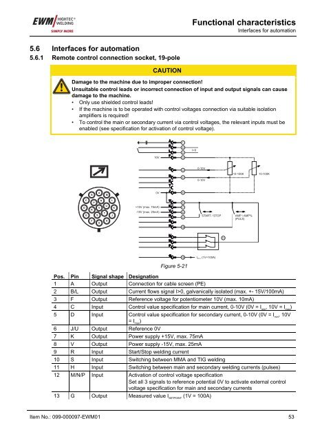
5.6.1 Remote control connection socket, 19-pole<br />
CAUTION<br />
Damage to the machine due to improper connection!<br />
Unsuitable control leads or incorrect connection of input and output signals can cause<br />
damage to the machine.<br />
• Only use shielded control leads!<br />
• If the machine is to be operated with control voltages connection via suitable isolation<br />
amplifiers is required!<br />
• To control the main or secondary current via control voltages, the relevant inputs must be<br />
enabled (see specification for activation of control voltage).<br />
10V<br />
A<br />
B<br />
L<br />
F<br />
1<br />
2<br />
2<br />
3<br />
I>0<br />
C<br />
D<br />
E<br />
4<br />
5<br />
0-10V<br />
0-10V<br />
10-100K<br />
10-100K<br />
T<br />
B<br />
A<br />
M<br />
0V<br />
J<br />
6<br />
D<br />
C<br />
E<br />
N<br />
P<br />
U<br />
V<br />
R<br />
T<br />
S<br />
F<br />
H<br />
G<br />
L<br />
J<br />
K<br />
+15V (max. 75mA)<br />
-15V (max. 25mA)<br />
U<br />
K<br />
V<br />
R<br />
S<br />
H<br />
6<br />
7<br />
8<br />
9<br />
10<br />
START / STOP<br />
AMP / AMP%<br />
(PULS)<br />
M<br />
N<br />
P<br />
11<br />
G<br />
12<br />
I<br />
SOLL<br />
(1V=100A)<br />
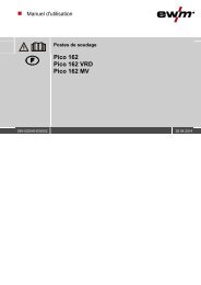
Figure 5-21<br />
Pos. Pin Signal shape Designation<br />
1 A Output Connection for cable screen (PE)<br />
2 B/L Output Current flows signal I>0, galvanically isolated (max. +- 15V/100mA)<br />
3 F Output Reference voltage for potentiometer 10V (max. 10mA)<br />
4 C Input Control value specification for main current, 0-10V (0V = I min<br />
, 10V = I max<br />
)<br />
5 D Input Control value specification for secondary current, 0-10V (0V = I min<br />
, 10V<br />
= I max<br />
)<br />
6 J/U Output Reference 0V<br />
7 K Output Power supply +15V, max. 75mA<br />
8 V Output Power supply -15V, max. 25mA<br />
9 R Input Start/Stop welding current<br />
10 S Input Switching between MMA and TIG welding<br />
11 H Input Switching between main and secondary welding currents (pulses)<br />
12 M/N/P Input Activation of control voltage specification<br />
Set all 3 signals to reference potential 0V to activate external control<br />
voltage specification for main and secondary currents<br />
13 G Output Measured value I SETPOINT<br />
(1V = 100A)<br />
Item No.: 099-000097-<strong>EWM</strong>01 53