tors actuators - Norgren Pneumatics. Motion Control Equipment ...
tors actuators - Norgren Pneumatics. Motion Control Equipment ...
tors actuators - Norgren Pneumatics. Motion Control Equipment ...

Create successful ePaper yourself
Turn your PDF publications into a flip-book with our unique Google optimized e-Paper software.
** Outstroke<br />
*** Center of gravity<br />
500<br />
400<br />
300<br />
200<br />
100<br />
( N )<br />
8080-8100<br />
8050-8063<br />
8040<br />
8032<br />
**<br />
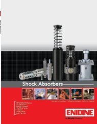
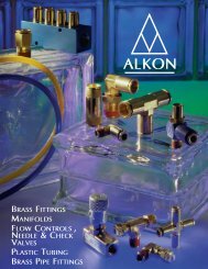
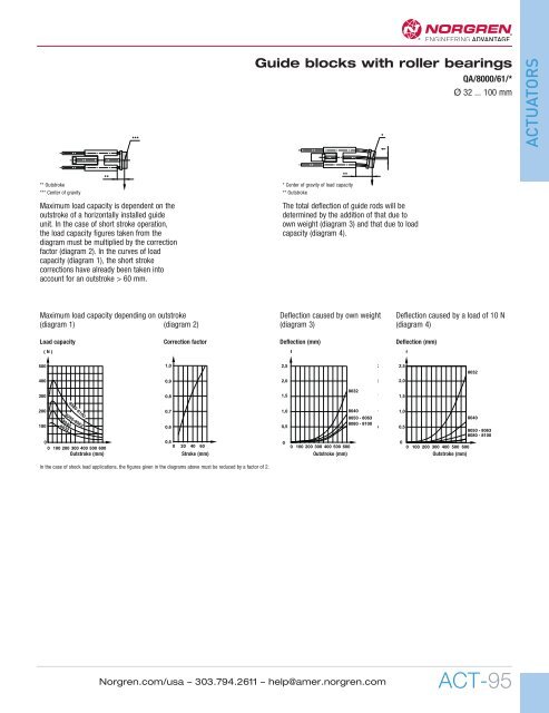
Maximum load capacity is dependent on the<br />
out stroke of a horizontally installed guide<br />
unit. In the case of short stroke operation,<br />
the load capacity figures taken from the<br />
diagram must be multiplied by the correction<br />
factor (diagram 2). In the curves of load<br />
capacity (diagram 1), the short stroke<br />
corrections have already been taken into<br />
account for an outstroke > 60 mm.<br />
0<br />
0 100 200 300 400 500 600<br />
Outstroke (mm)<br />
***<br />
0,5<br />
0 20 40 60<br />
0<br />
0<br />
0 100 200 300 400 500 600<br />
0 0 100 200 300 400 500 600<br />
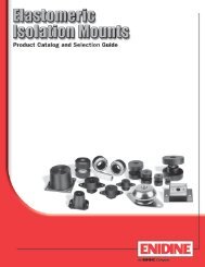
Guide blocks with roller bearings<br />
QA/8000/61/*<br />
Ø 32 ... 100 mm<br />
*<br />
**<br />
* Center of gravity of load capacity<br />
** Outstroke<br />
The total deflection of guide rods will be<br />
determined by the addition of that due to<br />
own weight (diagram 3) and that due to load<br />
capacity (diagram 4).<br />
f<br />
f<br />
1,0<br />
1<br />
2,5<br />
2 2,5<br />
8032<br />
0,9<br />
2,0<br />
2 2,0<br />
8032<br />
0,8<br />
0,7<br />
1,5<br />
1,0<br />
8040<br />
1<br />
1<br />
1,5<br />
1,0<br />
8050 - 8063<br />
8040<br />
0,6<br />
0,5<br />
8080 - 8100<br />
0 0,5<br />
8050 - 8063<br />
8080 - 8100<br />
Stroke (mm)<br />
Outstroke (mm)<br />
Outstroke (mm)<br />
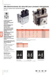
Maximum load capacity depending on outstroke Deflection caused by own weight Deflection caused by a load of 10 N<br />
(diagram 1) (diagram 2) (diagram 3) (diagram 4)<br />
Load capacity Correction factor Deflection (mm) Deflection (mm)<br />
f<br />
ACTUATORS<br />
In the case of shock load applications, the figures given in the diagrams above must be reduced by a factor of 2.<br />
<strong>Norgren</strong>.com/usa – 303.794.2611 – help@amer.norgren.com<br />
ACT-95