tors actuators - Norgren Pneumatics. Motion Control Equipment ...
tors actuators - Norgren Pneumatics. Motion Control Equipment ...
tors actuators - Norgren Pneumatics. Motion Control Equipment ...

You also want an ePaper? Increase the reach of your titles
YUMPU automatically turns print PDFs into web optimized ePapers that Google loves.
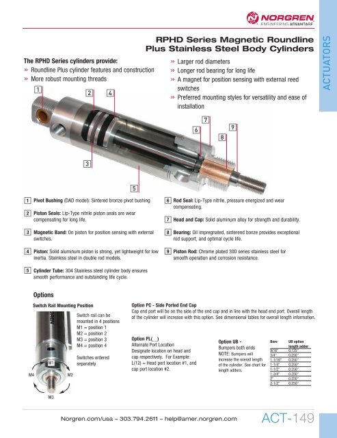
The RPHD Series cylinders provide:<br />
» Roundline Plus cylinder features and construction<br />
» More robust mounting threads<br />
1<br />
2<br />
4<br />
RPHD Series Magnetic Roundline<br />
Plus Stainless Steel Body Cylinders<br />
» Larger rod diameters<br />
» Longer rod bearing for long life<br />
» A magnet for position sensing with external reed<br />
switches<br />
» Preferred mounting styles for versatility and ease of<br />
installation<br />
ACTUATORS<br />
6<br />
7<br />
8<br />
9<br />
3<br />
5<br />
1<br />
2<br />
Pivot Bushing (DAD model): Sintered bronze pivot bushing<br />
Piston Seals: Lip-Type nitrile piston seals are wear<br />
compensating for long life.<br />
6<br />
7<br />
Rod Seal: Lip-Type nitrile, pressure energized and wear<br />
compensating.<br />
Head and Cap: Solid aluminum alloy for strength and durability.<br />
3<br />
Magnetic Band: On piston for position sensing with external<br />
switches.<br />
8<br />
Bearing: Oil impregnated, sinterend bonze provides exceptional<br />
rod support, and optimal cycle life.<br />
4<br />
Piston: Solid aluminum piston is strong, yet lightweight for low<br />
inertia. Stainless steel in double rod models.<br />
9<br />
Piston Rod: Chrome plated 300 series stainless steel for<br />
smooth operation and corrosion resistance.<br />
5<br />
Cylinder Tube: 304 Stainless steel cylinder body ensures<br />
smooth performance and outstanding life cycle.<br />
M4<br />
Options<br />
Switch Rail Mounting Position<br />
Switch rail can be<br />
mounted in 4 positions<br />
M1 = position 1<br />
M2 = position 2<br />
M3 = position 3<br />
M4 = position 4<br />
M1<br />
M2<br />
Switches ordered<br />
separately<br />
Option PC - Side Ported End Cap<br />
Cap end port will be on the side of the end cap and in line with the head end port. Overall length<br />
of the cylinder will increase with this option. See dimensional tables for overall length information.<br />
Option PL(__)<br />
Alternate Port Location<br />
Designate location on head and<br />
cap respectively. For Example:<br />
L(12) = Head port location #1, and<br />
cap port location #2.<br />
Option UB -<br />
Bumpers both ends<br />
NOTE: Bumpers will<br />
increase the overall length<br />
of the cylinder. See chart for<br />
length adders.<br />
Bore UB option<br />
length adder<br />
9/16" 0.125"<br />
3/4" 0.250"<br />
1-1/16" 0.250"<br />
1-1/4" 0.250"<br />
1-1/2" 0.250"<br />
1-3/4" 0.250"<br />
2" 0.250"<br />
2-1/2" 0.250"<br />
M3<br />
<strong>Norgren</strong>.com/usa – 303.794.2611 – help@amer.norgren.com<br />
ACT-149