tors actuators - Norgren Pneumatics. Motion Control Equipment ...
tors actuators - Norgren Pneumatics. Motion Control Equipment ...
tors actuators - Norgren Pneumatics. Motion Control Equipment ...

You also want an ePaper? Increase the reach of your titles
YUMPU automatically turns print PDFs into web optimized ePapers that Google loves.
<strong>Norgren</strong> NFPA Ecology Cylinders offer these advantages:<br />
1 2<br />
<strong>Norgren</strong> cylinders are prelubriated<br />
for non-lube<br />
operation.<br />
The piston rod is self-lubricated by the oilimpregnated<br />
rod bearing during operation.<br />
Lubrication between piston and cylinder barrel is<br />
derived from the polishing qualities of the<br />
reinforced Teflon ® wear ring.<br />
The low friction surfaces extend the life of the<br />
seals beyond normal expectations.<br />
Series EA and EJ cylinders are NFPA<br />
interchangeable and are available in many<br />
different mounting styles.<br />
Operates Quietly<br />
to Meet<br />
OSHA Specifications.<br />
Series EA and EJ cylinders provide substantial<br />
reductions in impact noise, which reduces overall<br />
machine noise and helps meet government regulations.<br />
Summary of Sound Levels in Decibels<br />
The summary of sound decibels chart illustrates<br />
the operating sound levels.<br />
The impact dampening qualities of the<br />
Piston Seals are guaranteed for ONE FULL YEAR!<br />
PSI Air Sound<br />
Cylinder Model<br />
Pressure J133B3 EJ155B3 J1133A3 EJ1155A3 A133B3 EA155B3 A1133A3 EA1155A3<br />
Level+ 5" x 6" 5" x 6" 2" x 6" 2" x 6" 5" x 6" 5" x 6" 2" x 6" 2" x 6"<br />
95 End++ 108 73 110 74 108 73 110 74<br />
PSI+ Side++ 112 84 110 81 112 84 110 81<br />
50 End++ 108 73 113 74 108 73 113 74<br />
PSI+ Side++ 113 85 110 81 113 85 110 81<br />
ACTUATORS<br />
3<br />
Energy Absorption<br />
Capacity of the Impact<br />
Dampening Seals<br />
Series EA and EJ cylinders have a impact<br />
dampening piston seal that accomplishes 80%<br />
of the actual load stopping. The air cushion<br />
accounts for only 20%. (A conventional air<br />
cushioning cylinder depends 100% on the<br />
compressibility of air to do the stopping.) The<br />
Ecology seal absorbs high impact loads<br />
allowing the effect of the air cushion to be<br />
reduced by using a larger air cushion bleed<br />
orifice. As a result the piston can move at a<br />
faster speed for a longer period of time before<br />
the Ecology seal does the final stopping.<br />
+ Peak sound pressure is given in decibels (dB)<br />
re:2 x 10 5 N/m 2 .<br />
++End position of mike was 3' on centerline from end of<br />
cylinder; side position of mike was 3' perpendicular to<br />
centerline abeam of end of cylinder.<br />
Energy Absorption Capacity of the Impact Dampening Seals<br />
*Usable Pounds Stoppable at the Following Piston Speeds<br />
This chart features the energy absorption capacity of the impact dampening piston seals<br />
with a Non-Adjustable cushions. For higher loads and velocities please refer to the Decel- Air Cushion.<br />
In/Sec<br />
Cylinder Bore<br />
1 1 /2 2 2 1 /2 3 1 /4 4 5 6 7 8 10 12<br />
6 155.6 275.5 499.8 969.3 1505.4 2603.2 4159.8 5794.2 8067.6 12,242 20,139<br />
12 38.4 68.1 123.4 239.7 372.6 644.8 1030.2 1435.8 2000.4 3026 4971<br />
18 16.7 29.7 53.7 104.6 162.8 282.1 450.6 628.7 876.8 1319.3 2162.1<br />
24 9.2 16.3 29.4 57.3 89.4 155.2 247.8 346.2 483.6 722 1179<br />
30 5.6 10.0 18.1 35.4 55.4 96.4 153.9 215.4 301.6 445.5 724<br />
36 3.7 6.7 11.9 23.5 37.0 64.5 102.9 144.4 202.7 295.3 476.8<br />
42 2.6 4.6 8.2 16.3 25.8 45.3 72.2 101.6 143.1 204.8 327.7<br />
48 1.8 3.2 5.8 11.7 18.6 32.8 52.2 73.8 104.4 146 231<br />
54 1.3 2.4 4.2 8.5 13.6 24.2 38.5 54.7 77.9 105.7 164.7<br />
60 1.0 1.8 3.0 6.2 10.1 18.1 28.7 41.1 58.9 76.9 117.2<br />
*The weight of the cylinder piston has been deducted from the figures shown above.<br />
Note: The use of Viton ® Seals limits the absorption of the impact dampening seals by 50%.<br />
Note: At 5 feet, cylinder sound levels would be less by 9 dB from<br />
side figure and 13 dB from end figure. The total noise emitted will<br />
depend on the structure to which the cylinder is attached. If it is<br />
mounted on a thin flat plate of considerable area, the noise will<br />
be increased by a sounding board effect.<br />
Energy absorption capacity of impact dampening piston seals w/ adjustable cushion.<br />
In/Sec<br />
Cylinder Bore<br />
1 1 /2 2 2 1 /2 3 1 /4 4 5 6 7 8 10 12<br />
6 279 495 899 1,744 2,709 4,685 7,486 10,429 4,520 22,035 36,250<br />
12 68 122 221 430 699 1,159 1,854 2,583 3,800 5,446 8,947<br />
18 30 53 95 187 291 507 810 1,130 1,576 2,374 3,891<br />
24 16 29 52 102 160 279 444 622 869 1,299 1,414<br />
30 10 18 32 63 99 172 275 387 541 801 1,303<br />
36 6.7 12 21.6 42 66 116 183 259 363 531 856<br />
42 4.7 8.3 14.7 29 46 81 129 181 257 367 588<br />
48 3.4 5.7 10.4 21 33 59 93 131 187 262 415<br />
54 2.3 4.3 7.6 15.3 24 43 68 97 138 189 295<br />
60 1.8 3.2 5.4 11 18 33 52 74 106 138 211<br />
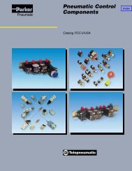
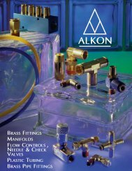
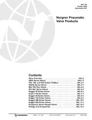
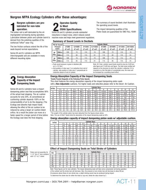
Piston and rod assembly for<br />
1-1/2" thru 5" bore cylinders<br />
with 1/2" to 2" stroke<br />
Effect of Impact Dampening Seals on Total Stroke of Cylinders<br />
PSI<br />
Cylinder Bore<br />
1 1 /2 2 2 1 /2 3 1 /4 4 5 6 7 8 10 12<br />
0 .14 .15 .17 .19 .22 .25 .28 .32 .32 .36 .40<br />
20 .10 .10 .12 .14 .16 .18 .20 .22 .22 .24 .26<br />
40 .07 .07 .08 .09 .10 .12 .13 .14 .14 .15 .16<br />
60 .04 .04 .05 .05 .06 .07 .07 .08 .08 .09 .10<br />
80 .02 .02 .02 .02 .03 .03 .03 .04 .04 .04 .04<br />
100 0 0 0 0 0 0 0 0 0 0 0<br />
Note: These figures are for new cylinders. The impact dampening seals will take some compression set during operation<br />
of the cylinder and the stroke loss will decrease. Also, the pressure at zero stroke loss will decrease to about 80 psi.<br />
At pressures above those of zero stroke loss, a slight clicking sound may be produced during impact.<br />
To determine the stroke loss for either the head or cap end, divide the value shown by 2.<br />
<strong>Norgren</strong>.com/usa – 303.794.2611 – help@amer.norgren.com<br />
ACT-11