tors actuators - Norgren Pneumatics. Motion Control Equipment ...
tors actuators - Norgren Pneumatics. Motion Control Equipment ...
tors actuators - Norgren Pneumatics. Motion Control Equipment ...

Create successful ePaper yourself
Turn your PDF publications into a flip-book with our unique Google optimized e-Paper software.
Features<br />
● Lintra®-Lite rodless cylinders require less space for<br />
installation since the stroke of the cylinder is contained within the length of<br />
the cylinder itself.<br />
● Non-rotating load carrying capability without additional guide rods and<br />
bearings.<br />
● Rodless design means there is no rod that can buckle or kink.<br />
● Equal forces can be applied to each stroke direction.<br />
● All stroke lengths are custom made to customer requirements.<br />
● Stroke lengths are available up to 236" (6000mm). For longer stroke<br />
lengths, consult factory.<br />
LINTRA®-Lite rodless cylinders<br />
A44000<br />
Double acting<br />
Ø 25 ... 40 mm<br />
● Lintra®-Lite features a choice of bore sizes:<br />
Ø 1" = 0.984" (Ø 25mm)<br />
Ø 1-1/4" = 1.260" (Ø 32mm)<br />
Ø 1-1/2" = 1.575" (Ø 40mm)<br />
● Cushion adjustment optional at both ends of the cylinder.<br />
● Magnetic piston optional.<br />
● Integral switch rail on both sides of the extrusion.<br />
● Main components are made of anodized, corrosion resistant<br />
aluminum, with zinc plated steel integral foot mount end covers.<br />
● Velocities up to 4.9 ft/sec (1.5 m/s) are achievable.<br />
● The Lintra®-Lite is designed for easy maintenance.<br />
● Polyurethane seals provide long life.<br />
ACTUATORS<br />
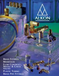
The Extruded Tube of the LINTRA¨−LITE Series A44000 Cylinder<br />
Extrusion configuration<br />
resists flex and provides<br />
superior <strong>tors</strong>ional stiffness,<br />
with little deflection<br />
Integral switch rails for<br />
position sensing switches<br />
Extruded for<br />
self−forming screws<br />
Clear coat anodized<br />
corrosion resistant<br />
aluminum<br />
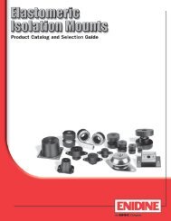
Cylinder Deflection<br />
Deflection due to external load.<br />
External Load<br />
Force<br />
(N)<br />
F (N)<br />
Lbs.<br />
(2000) 2000 450<br />
(1000) 1000 225<br />
(500) 112.5 500<br />
(200) 200 45<br />
(100) 22.5 100<br />
50<br />
(50) 11.25<br />
10<br />
(10) 2.25<br />
Deflection f1 = f1= .039 1 mm (1mm)<br />
1" (25mm)<br />
(1) .2251<br />
0 39 1000591500792000 98 118 3000 157 4000197 5000 236 inches 6000<br />
(1000) (1500) (2000) (2500) 2500 (3000) (4000) (5000) Supported (6000) (mm) length (mm)<br />
Cylinder ø1-1/4" (32mm), stroke length 138" (3500mm), external load 45 lbs. (200 N).<br />
Maximum distance between supports = 59 inches (1500mm) (see diagram). Therefore<br />
additional support is required.<br />
ø40<br />
ø32<br />
ø25<br />
inches (mm) between supports<br />
11/2" (40mm)<br />
11/4" (32mm)<br />
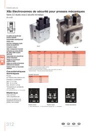
Deflection due to cylinder weight.<br />
Deflection<br />
f<br />
f2<br />
2 (mm)<br />
(mm) inch<br />
(2) .079<br />
2<br />
(1) .039 1<br />
(0.6) 0,6 .024<br />
(0.4) 0,4 .016<br />
ø25<br />
ø32<br />
ø40<br />
(0.1) 0,1 .004<br />
0 39 79 98 118 157 197 236 inches<br />
1000 2000 3000 4000 5000 6000<br />
(1000) (2000) (2500) (3000) (4000) (5000) (6000) (mm)<br />
2500<br />
Supported Supported length (mm)<br />
Cylinder ø 40mm, external force 25 lbs. force (120 N), distance between<br />
supports 98 inches (2500mm).<br />
Required: Total deflection<br />
1.Deflection due to external force (f1): See diagram<br />
.039"/20.23 lbs. (1mm/90 N) x 25 lbs. (120 N) .051" (1.3mm)<br />
2.Deflection due to cylinder weight (f2): See diagram +.024" (0.6mm)<br />
Total deflection: .075" (1.9mm)<br />
Maximum permitted deflection:<br />
f1 + f2 √ .039 inches (1mm) per 39.37 inches (1000mm) stroke. Result:<br />
.075 inches (1.9mm) are below the maximum permitted deflection of .098<br />
inches (2.5mm).<br />
<strong>Norgren</strong>.com/usa – 303.794.2611 – help@amer.norgren.com<br />
ACT-131