tors actuators - Norgren Pneumatics. Motion Control Equipment ...
tors actuators - Norgren Pneumatics. Motion Control Equipment ...
tors actuators - Norgren Pneumatics. Motion Control Equipment ...

You also want an ePaper? Increase the reach of your titles
YUMPU automatically turns print PDFs into web optimized ePapers that Google loves.
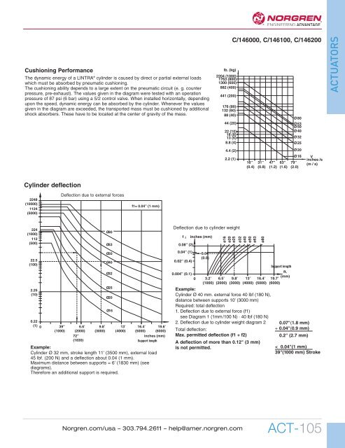
Cushioning Performance<br />
The dynamic energy of a LINTRA ® cylinder is caused by direct or partial external loads<br />
which must be absorbed by pneumatic cushioning.<br />
The cushioning ability depends to a large extent on the pneumatic circuit (e. g. counter<br />
pressure, pre-exhaust). The values given in the diagram were tested with an operation<br />
pressure of 87 psi (6 bar) using a 5/2 control valve. When installed horizontally, depending<br />
upon the speed, dynamic energy can be absorbed by the cylinder. Whenever the values<br />
given in the diagram are exceeded, the transported mass must be cushioned by additional<br />
shock absorbers. These have to be located at the center of gravity of the mass.<br />
lb. (kg)<br />
2204 (1000)<br />
1763 (800)<br />
1300 (600)<br />
882 (400)<br />
441 (200)<br />
176 (80)<br />
132 (60)<br />
88 (40)<br />
44 (20)<br />
22 (10)<br />
18 (8)<br />
13 (6)<br />
8.8 (4)<br />
4.4 (2)<br />
2.2 (1)<br />
C/146000, C/146100, C/146200<br />
16”<br />
(0.4)<br />
31”<br />
(0.8)<br />
47”<br />
(1.2)<br />
63”<br />
(1.6)<br />
Ø 80<br />
Ø 63<br />
50<br />
Ø 40<br />
Ø 32<br />
Ø 25<br />
Ø 20<br />
Ø 16<br />
79”<br />
(2.0)<br />
V<br />
inches /s<br />
(m / s)<br />
ACTUATORS<br />
Cylinder deflection<br />
2248<br />
(10000)<br />
1124<br />
(5000)<br />
Deflection due to external forces<br />
f1= 0.04” (1 mm)<br />
224<br />
(1000)<br />
112<br />
(500)<br />
22.5<br />
(100)<br />
2.25<br />
(10)<br />
0.22<br />
(1) 0 39” 6.6’<br />
(1000) (2000)<br />
72”<br />
(1830)<br />
9.8’<br />
(3000)<br />
13’<br />
(4000)<br />
16.4’<br />
(5000)<br />
inches (mm)<br />
Support length<br />
Example:<br />
Cylinder Ø 32 mm, stroke length 11' (3500 mm), external load<br />
45 lbf. (200 N) and a deflection about 0.04 (1 mm).<br />
Maximum distance between supports = 6' (1830 mm) (see<br />
diagrams).<br />
Therefore an additional support is required.<br />
Ø80<br />
Ø63<br />
Ø50<br />
Ø40<br />
Ø32<br />
Ø25<br />
Ø20<br />
Ø16<br />
19.6’<br />
(6000)<br />
Deflection due to cylinder weight<br />
f<br />
0.004” (0.1)<br />
0<br />
2<br />
0.08” (2)<br />
0.04” (1)<br />
0.02” (0.4)<br />
inches (mm)<br />
0.04<br />
(0.9)<br />
3.2’<br />
(1000)<br />
6.5’<br />
(2000)<br />
9.8’<br />
(3000)<br />
13’<br />
(4000)<br />
16.4’<br />
(5000)<br />
Example:<br />
Cylinder Ø 40 mm. external force 40 lbf (180 N),<br />
distance between supports 10' (3000 mm)<br />
Required: total deflection<br />
1. Deflection due to external force (f1)<br />
see Diagram 1 (1mm/100 N) · 40 lbf (180 N)<br />
2. Deflection due to cylinder weight diagram 2<br />
Total deflection:<br />
Max. permitted deflection (f1 + f2)<br />
A deflection of more than 0.12" (3 mm)<br />
is not permitted.<br />
Support length<br />
19.7’<br />
(6000)<br />
ft.<br />
(mm)<br />
0.07"(1.8 mm)<br />
+ 0.04"(0.9 mm)<br />
0.2" (2.7 mm)<br />
< 0.04"(1 mm)<br />
39"(1000 mm) Stroke<br />
<strong>Norgren</strong>.com/usa – 303.794.2611 – help@amer.norgren.com<br />
ACT-105