tors actuators - Norgren Pneumatics. Motion Control Equipment ...
tors actuators - Norgren Pneumatics. Motion Control Equipment ...
tors actuators - Norgren Pneumatics. Motion Control Equipment ...

Create successful ePaper yourself
Turn your PDF publications into a flip-book with our unique Google optimized e-Paper software.
ACTUATORS<br />
C/146000, C/146100, C/146200<br />
Theoretical forces, air consumption, cushioning length, holding forces<br />
Cylinder Theoretical forces lbf (N) Air consumption ft 3 /in. (l/cm) Cushioning length Holding forces lbf. (N) of brake (on dry braking surface)<br />
Ø mm at 87 psi (6 bar) of stroke at 87 psi (6 bar) inches (mm) active (L3) at 87 psi (6 bar) passive (L4)<br />
16 27 (120) 0.001 (0.014) 0.5 (12) – –<br />
20 42 (188) 0.002 (0.022) 1 (26) – –<br />
25 66 (294) 0.003 (0.035) 1 (26) 112 (5000 50 (220)<br />
32 108 (482) 0.005 (0.056) 1.4 (35) 202 (900) 84 (375)<br />
40 170 (754) 0.008 (0.088) 2 (50) 337 (1500) 141 (630)<br />
50 265 (1178) 0.012 (0.137) 2.3 (60) 562 (2500) 225 (1000)<br />
63 420 (1870) 0.02 (0.218) 2.8 (70) 899 (4000) 371 (1650)<br />
80 678 (3016) 0.03 (0.350) 3 (75) – –<br />
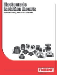
C/146000, C/146100, C/146200<br />
C/146200/P<br />
Internal guide External adjustable guide Precision roller guide Added caged ball linear<br />
C/146000 C/146100 C/146200 motion guide C/146200/P<br />
Fy Fz Mx My Mz Fy, Fz Mx My, Mz Fy Fz Mx My, Mz Fy, Fz Mx My, Mz<br />
lbf. lbf. lbf in. lbf in. lbf in. lbf. lbf in. lbf in. lbf. lbf. lbf in. lbf in. lbf. lbf in. lbf in.<br />
Ø mm (N) (N) (Nm) (Nm) (Nm) (N) (Nm) (Nm) (N) (N) (Nm) (Nm) (N) (Nm) (Nm)<br />
16 9 27 2.7 33.6 9.7 45 17.7 48.7 – – – – – – –<br />
(40) (120) (0.3) (3.8) (1.1) (200) (2) (5.5) – – – – – – –<br />
20 20 63 8.0 106.2 31.9 106 53.1 159.3 – – – – – – –<br />
(90) (280) (0.9) (12) (3.6) (470) (6) (18) – – – – – – –<br />
25 28 87 13.3 168.2 49.6 133 79.7 247.8 133 266 115.1 371.7 450 283 1770<br />
(125) (385) (1.5) (19) (5.6) (590) (9) (28) (590) (1180) (13) (42) (2000) (32) (200)<br />
32 37 113 26.6 292.1 88.5 176 150.5 380.6 176 351 221.3 566.5 899 566 3540<br />
(165) (500) (3) (33) (10) (780) (17) (43) (780) (1560) (25) (64) (4000) (64) (400)<br />
40 74 223 57.5 743.5 212.4 360 345.2 973.6 338 676 513.4 1416.2 899 566 3540<br />
(330) (990) (6.5) (84) (24) (1600) (39) (110) (1500) (3000) (58) (160) (4000) (64) (400)<br />
50 99 297 97.4 1062.1 309.8 450 575.3 1416.2 450 901 858.6 2124.3 1798 1593 7080<br />
(440) (1320) (11) (120) (35) (2000) (65) (160) (2000) (4000) (97) (240) (8000) (180) (800)<br />
63 155 450 177.0 2124.3 619.6 721 1062.1 3097.9 721 1441 1593.2 4602.6 1798 1593 7966<br />
(690) (2000) (20) (240) (70) (3200) (120) (350) (3200) (6400) (180) (520) (8000) (180) (900)<br />
80 176 518 239.0 3186.4 885.1 878 1593.2 4602.6<br />
(780) (2300) (27) (360) (100) (3900) (180) (520) – – – – – – –<br />
Loading values applicable to a speed of √0.2 m/s. Maximum working life is normally reached below a speed of 1 m/s.<br />
* The forces and moments refers to the center of the guide. They must not be exceeded in dynamic applications.<br />
Loading values for LINTRA ® cylinders<br />
with double carriages<br />
The values given in the table below show the single forces in the<br />
directions Fy and Fz and the maximum moments Mx, My and Mz.<br />
All values are applicable only for speeds of max. 0.2 m/s.<br />
A requirement for using these values is a constant movement (no<br />
jerking) of the mass over the whole stroke length of the cylinder.<br />
The reference point from which the moments for all cylinders should<br />
be calculated is the center line of the pistons.<br />
When a LINTRA ® cylinder has to take several loads and moments. an<br />
additional calculation is necessary using this formula:<br />
Mx My Mz Fy Fz<br />
+ + + +