advanced drainage system - Polypipe
advanced drainage system - Polypipe
advanced drainage system - Polypipe

Create successful ePaper yourself
Turn your PDF publications into a flip-book with our unique Google optimized e-Paper software.
General Structural Design 3.2<br />
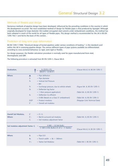
Methods of flexible pipe design<br />
Numerous methods of pipeline design have been developed, influenced by the prevailing conditions in the country in which<br />
the development occurred. The most established method of design for flexible pipes is that produced by Spangler. Although<br />
originally developed for large diameter thin-walled corrugated steel culverts under embankment conditions, the method has<br />
been adopted in much of the world for all types of flexible pipes. This design method is recommended for the UK in BS EN<br />
1295: Part 1 and forms the basis of this section.<br />
Prediction of long term pipe deformation<br />
BS EN 1295-1:1998; “Structural design of buried pipelines under various conditions of loading.”; is the standard used<br />
within the UK in assessing pipeline design. The various different types of pipe <strong>system</strong>s available are differentiated<br />
according to cross-sectional behaviour as rigid, semi-rigid or flexible.<br />
For design purposes, the flexible calculation procedure is normally used for pipes manufactured from steel,<br />
thermoplastic and GRP.<br />
The following procedure is extracted from BS EN 1295-1, Clause NA.6:<br />
Ovalization, Kx [(DLPe)+Ps]<br />
=<br />
(Clause NA.6.2.4; BS EN 1295-1)<br />
D (8EI/D 3 )+ (0.061E’)<br />
Where:<br />
= Pipe deflection<br />
D = Pipe diameter<br />
Pe<br />
= Vertical Soil Pressure<br />
= H<br />
PS = Surcharge pressure, due to vehicle wheels (Figure NA. 6; BS EN 1295-1)<br />
DL<br />
Kx<br />
∝<br />
= Deflection lag factor<br />
= 1 (Non pressure application) (Table NA. 6; BS EN 1295-1)<br />
= Deflection Co-efficient<br />
= 0.083 (Based on a Class S1 embedment) (Table NA. 6; BS EN 1295-1)<br />
EI/D 3 = Product modulus (<strong>Polypipe</strong> Civils Technical Data)<br />
E’ = Overall soil modulus<br />
Overall Soil Modulus, E’ = E’2 CL<br />
Where: E’2 = Bed & surround soil modulus (Table NA. 6; BS EN 1295-1)<br />
CL<br />
= Soil modulus adjustment factor<br />
Soil modulus adjustment factor, CL =<br />
0.985 + (0.544 Bd/Bc)<br />
[1.985-0.456 (Bd/Bc)] (E’2/E’3) - [1-(Bd/Bc)]<br />
(Clause NA.6.2.4; BS EN 1295-1)<br />
Where: Bc = Pipe O.D<br />
Bd<br />
= Trench width = Bc + 300mm<br />
E’3 = Native Soil Modulus (Table NA.1; BS EN 1295-1)<br />
49