advanced drainage system - Polypipe
advanced drainage system - Polypipe
advanced drainage system - Polypipe
Create successful ePaper yourself
Turn your PDF publications into a flip-book with our unique Google optimized e-Paper software.
General Properties 3.4<br />
Minimum Gradients<br />
Sedimentation reduces a pipe <strong>system</strong>s hydraulic capacity, increases pollution concentration and in extreme cases<br />
may lead to partial or complete blockages. Minimum pipe gradients are therefore specified to ensure the pipe flow<br />
regularly achieves a ‘self-cleansing’ velocity, limiting long-term sedimentation.<br />
A velocity flow of 0.75m/s is typically used as the minimum self-cleansing velocity in <strong>system</strong> design. However, certain<br />
applications are required to comply with particular codes of practice.<br />
• Non-adoptable <strong>drainage</strong>, within a properties curtilage, is defined by The Building Regulations. Prescribing specific<br />
minimum pipe gradients for small diameter sewers.<br />
Sewer <strong>system</strong>s proposed for adoption should be designed in accordance with Sewers For Adoption (6th Edition). It<br />
specifies that foul sewers should achieve a minimum flow velocity of 0.75m/s at one-third design flow and surface<br />
water sewers 1.0m/s at pipe full flow.<br />
Design Example<br />
Pipe Size Determination<br />
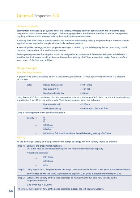
A pipeline is to carry a discharge of 0.015 cubic metres per second (15 litres per second) when laid at a gradient<br />
of 1 in 180.<br />
Data: Design discharge (Q) = 0.015m 3 /s<br />
Pipe gradient (S) = 1 in 180<br />
Roughness height (ks)<br />
= 0.6mm<br />
Using Figure 3.3.3 for ks = 0.6mm, find the intersection point of a discharge of 0.015m 3 s -1 on the left hand scale and<br />
a gradient of 1 in 180 on the bottom scale. The intersection point yields the following:<br />
Pipe size selected<br />
Discharge capacity<br />
= 225mm<br />
= 0.038m 3 /s at full bore flow<br />
Using a rearrangement of the continuity equation,<br />
Velocity =<br />
Q<br />
A<br />
Velocity<br />
= 0.038m 3 /s<br />
0.040m 2<br />
= 0.95m 3 /s at full bore flow (above the self-cleansing velocity of 0.75m/s<br />
As the discharge capacity of the pipe exceeds the design discharge, the flow velocity should be checked.<br />
Step 1: Calculate the proportional discharge.<br />
This is the ratio of the design discharge to the full bore flow discharge capacity.<br />
Proportional discharge<br />
=<br />
0.015m 3 /s<br />
0.038m 3 /s<br />
= 0.39<br />
Step 2: Using Figure 3.4.1, the proportional discharge curve (read on the bottom scale) yields a proportional depth<br />
of 0.44 (read on the left scale). A proportional depth of 0.44 yields a proportional velocity of 0.95.<br />
Step 3: Calculate the velocity of the design discharge by multiplying the full bore flow velocity by the<br />
proportional velocity.<br />
0.95 x 0.95m/s = 0.90m/s<br />
64<br />
Therefore, the velocity of flow at the design discharge exceeds the self-cleansing velocity.


