advanced drainage system - Polypipe
advanced drainage system - Polypipe
advanced drainage system - Polypipe

You also want an ePaper? Increase the reach of your titles
YUMPU automatically turns print PDFs into web optimized ePapers that Google loves.
General Hydraulic Design 3.3<br />
Hydraulic Properties<br />
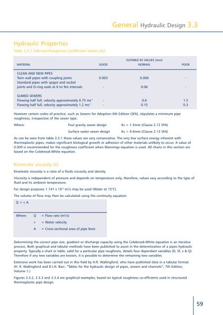
Table 3.3.1 Selected Roughness Coefficient Values (ks)<br />
Suitable ks values (mm)<br />
Material Good Normal Poor<br />
Clean and new pipes<br />
Twin wall pipes with coupling joints 0.003 0.006 -<br />
Standard pipes with spigot and socket<br />
joints and O-ring seals at 6 to 9m intervals - 0.06 -<br />
Slimed sewers<br />
Flowing half full, velocity approximately 0.75 ms -1 - 0.6 1.5<br />
Flowing half full, velocity approximately 1.2 ms -1 - 0.15 0.3<br />
However certain codes of practice, such as Sewers for Adoption 6th Edition (SFA), stipulates a minimum pipe<br />
roughness, irrespective of the sewer type.<br />
Where: Foul gravity sewer design Ks = 1.5mm (Clause 2.12 SFA)<br />
Surface water sewer design<br />
Ks = 0.6mm (Clause 2.13 SFA)<br />
As can be seen from table 3.3.1 these values are very conservative. The very low surface energy inherent with<br />
thermoplastic pipes, makes significant biological growth or adhesion of other materials unlikely to occur. A value of<br />
0.009 is recommended for the roughness coefficient when Mannings equation is used. All charts in this section are<br />
based on the Colebrook-White equation.<br />
Kinematic viscosity (v)<br />
Kinematic viscosity is a ratio of a fluids viscosity and density.<br />
Viscosity is independent of pressure and depends on temperature only, therefore, values vary according to the type of<br />
fluid and its ambient temperature.<br />
For design purposes 1.141 x 10 -6 m 2 /s may be used (Water at 15°C).<br />
The volume of flow may then be calculated using the continuity equation.<br />
Q = n A<br />
Where: Q = Flow rate (m 3 /s)<br />
n<br />
A<br />
= Water velocity<br />
= Cross-sectional area of pipe bore<br />
Determining the correct pipe size, gradient or discharge capacity using the Colebrook-White equation is an iterative<br />
process. Both graphical and tabular methods have been published to assist in the determination of a pipes hydraulic<br />
property. Typically a chart or table, valid for a particular pipe roughness, details four dependant variables (D, Sf, v & Q).<br />
Therefore if any two variables are known, it is possible to determine the remaining two variables.<br />
Extensive work has been carried out in this field by H.R. Wallingford, who have published data in a tabular format.<br />
(H. R. Wallingford and D.I.H. Barr; “Tables for the hydraulic design of pipes, sewers and channels”; 7th Edition,<br />
Volume 1.)<br />
Figures 3.3.2, 3.3.3 and 3.3.4 are graphical examples, based on typical roughness co-efficients used in structured<br />
thermoplastic pipe design.<br />
59