You also want an ePaper? Increase the reach of your titles
YUMPU automatically turns print PDFs into web optimized ePapers that Google loves.
Real Time Analyzer Controls<br />
Real Time Analyzer Controls<br />
page 12<br />
<strong>Ivie</strong> <strong>IE</strong>-<strong>33</strong> & <strong>IE</strong>-<strong>35</strong> <strong>Manual</strong><br />
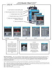
Stylus Buttons: The <strong>IE</strong>-<strong>33</strong> and <strong>IE</strong>-<strong>35</strong> are several instruments in the same package: Real Time Analyzer,<br />
Sound Level Meter, Signal Generator, Oscilloscope etc. One of their most powerful functions is Real Time<br />
Analyzer (RTA). To make operation simple and intuitive, the most often used controls for the RTA are labeled<br />
stylus buttons. The illustration across the page shows the stylus buttons associated with the RTA. Displays of<br />
octave, third octave, sixth octave and maximum resolution (2048 FFT data points) are selectable as shown.<br />
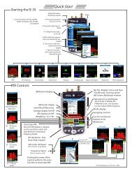
iPAQ and Axim Buttons: The <strong>IE</strong>-<strong>33</strong> and <strong>IE</strong>-<strong>35</strong> make use of the buttons found on the iPAQ and the Axim. Their<br />
use is defined as shown across the page. The joy stick up/down function can be used to quickly adjust the display<br />
to bring the signal to the center of the screen. Either the stylus “Zoom In” and “Zoom Out” buttons, or the<br />
push buttons to the right of the joy stick can be used to adjust screen resolution.<br />
Pop-up Menus: Additionally, pop-up menus provide more features and selection capability. Tapping the<br />
“Function” menu on the bottom of the screen with the stylus allows the selection of the RTA function. The various<br />
displays of the RTA function are shown in the illustration across the page. Below RTA in the Function menu<br />
is “RTA LEDs.” Selecting this function will provide a display that looks like an LED bar graph that many are so<br />
familiar with. The advantage of this display is that the screen resolution can be adjusted so each LED represents<br />
1dB, 2dB or 3dB. These increments are very useful when equalizing a sound system.<br />
To set the level at the center of the screen (dB Level) and to adjust the dynamic range of the screen (dB per<br />
Division), tap the "Display" menu. Next, from the pop-up menu, select "Set dB Scale." The window shown on<br />
the <strong>IE</strong>-<strong>33</strong> at the bottom of the opposite page shows this feature (the <strong>IE</strong>-<strong>35</strong> is identical). The other functions of<br />
the pop-up menus are covered in detail in other sections of this manual.<br />
Decay: Display speed (averaging time) is controlled by the stylus button titled “Decay.” Decay 1 is the fastest<br />
response time available, with Decay 2 somewhat slower and Decay 3 being the slowest. Decay 3 is intended<br />
for use with pink noise.<br />
Start/Stop Stylus Button: This button stops (freezes) the RTA and SPL displays and starts them again when<br />
tapped a second time.<br />
RTA Display On/Off: The RTA display can be turned on or off using the stylus button illustrated across the<br />
page. Green button indicates “On,” and brown button indicates “Off.”<br />
Average Display On/Off: The Average display (when the Average function is active) can be turned on or off<br />
using the stylus button. Green button indicates “On,” and brown button indicates “Off.” A red button indicates<br />
the Average function is not active.<br />
Memory Stylus Buttons: The <strong>IE</strong>-<strong>33</strong> and <strong>IE</strong>-<strong>35</strong> have 9 “scratch” memories (see the “Memory” section of this<br />
manual for more information on memory and data storage). To store data in a scratch memory, tap the numbered<br />
stylus button. A “snapshot” will be stored. If you are in the Average mode, the average curve will be<br />
stored. When a memory is empty, its stylus button is red. Memories with data in them have green stylus buttons<br />
when being displayed and brown when not being displayed. The last memory stored or activated for display<br />
always has a blue stylus button. Several memories can be displayed simultaneously and each will have its<br />
own color on the display so it can be differentiated.<br />
Preferred Curve: The last stylus button in the row of memory status buttons is the memory status button for<br />
“Preferred Curve.” This is a very powerful function and its use is covered extensively in the section of this manual<br />
titled “RTA -Preferred Curve, Display Weighting, LED Display.”<br />
SPL Readout Stylus Button: Tapping the SPL readout area will cause the analyzer to step through its electrical<br />
measurement modes. This is very useful for looking at voltage levels simultaneously with spectral content.<br />
Obviously, this feature should be used when measuring electrical signal, not acoustic signals through the mic.