Lab 2.5.1: Basic PPP Configuration Lab
Lab 2.5.1: Basic PPP Configuration Lab
Lab 2.5.1: Basic PPP Configuration Lab

Create successful ePaper yourself
Turn your PDF publications into a flip-book with our unique Google optimized e-Paper software.
CCNA Exploration<br />
Accessing the WAN: Frame Relay<br />
<strong>Lab</strong> 3.5.1 <strong>Basic</strong> Frame Relay<br />
_____________________________________________________________________________<br />
_____________________________________________________________________________<br />
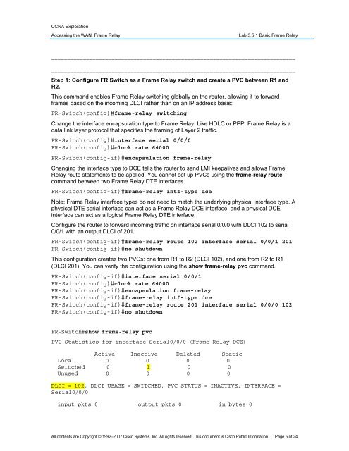
Step 1: Configure FR Switch as a Frame Relay switch and create a PVC between R1 and<br />
R2.<br />
This command enables Frame Relay switching globally on the router, allowing it to forward<br />
frames based on the incoming DLCI rather than on an IP address basis:<br />
FR-Switch(config)#frame-relay switching<br />
Change the interface encapsulation type to Frame Relay. Like HDLC or <strong>PPP</strong>, Frame Relay is a<br />
data link layer protocol that specifies the framing of Layer 2 traffic.<br />
FR-Switch(config)#interface serial 0/0/0<br />
FR-Switch(config)#clock rate 64000<br />
FR-Switch(config-if)#encapsulation frame-relay<br />
Changing the interface type to DCE tells the router to send LMI keepalives and allows Frame<br />
Relay route statements to be applied. You cannot set up PVCs using the frame-relay route<br />
command between two Frame Relay DTE interfaces.<br />
FR-Switch(config-if)#frame-relay intf-type dce<br />
Note: Frame Relay interface types do not need to match the underlying physical interface type. A<br />
physical DTE serial interface can act as a Frame Relay DCE interface, and a physical DCE<br />
interface can act as a logical Frame Relay DTE interface.<br />
Configure the router to forward incoming traffic on interface serial 0/0/0 with DLCI 102 to serial<br />
0/0/1 with an output DLCI of 201.<br />
FR-Switch(config-if)#frame-relay route 102 interface serial 0/0/1 201<br />
FR-Switch(config-if)#no shutdown<br />
This configuration creates two PVCs: one from R1 to R2 (DLCI 102), and one from R2 to R1<br />
(DLCI 201). You can verify the configuration using the show frame-relay pvc command.<br />
FR-Switch(config-if)#interface serial 0/0/1<br />
FR-Switch(config)#clock rate 64000<br />
FR-Switch(config-if)#encapsulation frame-relay<br />
FR-Switch(config-if)#frame-relay intf-type dce<br />
FR-Switch(config-if)#frame-relay route 201 interface serial 0/0/0 102<br />
FR-Switch(config-if)#no shutdown<br />
FR-Switch#show frame-relay pvc<br />
PVC Statistics for interface Serial0/0/0 (Frame Relay DCE)<br />
Active Inactive Deleted Static<br />
Local 0 0 0 0<br />
Switched 0 1 0 0<br />
Unused 0 0 0 0<br />
DLCI = 102, DLCI USAGE = SWITCHED, PVC STATUS = INACTIVE, INTERFACE =<br />
Serial0/0/0<br />
input pkts 0 output pkts 0 in bytes 0<br />
All contents are Copyright © 1992–2007 Cisco Systems, Inc. All rights reserved. This document is Cisco Public Information. Page 5 of 24