Lab 2.5.1: Basic PPP Configuration Lab
Lab 2.5.1: Basic PPP Configuration Lab
Lab 2.5.1: Basic PPP Configuration Lab

Create successful ePaper yourself
Turn your PDF publications into a flip-book with our unique Google optimized e-Paper software.
CCNA Exploration<br />
Accessing the WAN: ACLs<br />
<strong>Lab</strong> 5.5.1 <strong>Basic</strong> Access Control Lists<br />
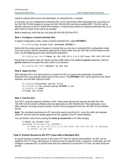
needs to enforce both source and destination, an extended ACL is needed.<br />
In this task, you are configuring an extended ACL on R1 that blocks traffic originating from any device on<br />
the 192.168.10.0/24 network to access the 209.165.200.255 host (the simulated ISP). This ACL will be<br />
applied outbound on the R1 Serial 0/0/0 interface. A typical best practice for applying extended ACLs is to<br />
place them as close to the source as possible.<br />
Before beginning, verify that you can ping 209.165.200.225 from PC1.<br />
Step 1: Configure a named extended ACL.<br />
In global configuration mode, create a named extended ACL called EXTEND-1.<br />
R1(config)#ip access-list extended EXTEND-1<br />
Notice that the router prompt changes to indicate that you are now in extended ACL configuration mode.<br />
From this prompt, add the necessary statements to block traffic from the 192.168.10.0/24 network to the<br />
host. Use the host keyword when defining the destination.<br />
R1(config-ext-nacl)#deny ip 192.168.10.0 0.0.0.255 host 209.165.200.225<br />
Recall that the implicit “deny all” blocks all other traffic without the additional permit statement. Add the<br />
permit statement to ensure that other traffic is not blocked.<br />
R1(config-ext-nacl)#permit ip any any<br />
Step 2: Apply the ACL.<br />
With standard ACLs, the best practice is to place the ACL as close to the destination as possible.<br />
Extended ACLs are typically placed close to the source. The EXTEND-1 ACL will be placed on the Serial<br />
interface, and will filter outbound traffic.<br />
R1(config)#interface serial 0/0/0<br />
R1(config-if)#ip access-group EXTEND-1 out<br />
R1(config-if)#end<br />
R1#copy run start<br />
Step 3: Test the ACL.<br />
From PC1, ping the loopback interface on R2. These pings should fail, because all traffic from the<br />
192.168.10.0/24 network is filtered when the destination is 209.165.200.225. If the destination is any<br />
other address, the pings should succeed. Confirm this by pinging R3 from the 192.168.10.0/24 network<br />
device.<br />
Note: The extended ping feature on R1 cannot be used to test this ACL, since the traffic will originate<br />
within R1 and will never be tested against the ACL applied to the R1 serial interface.<br />
You can further verify this by issuing the show ip access-list on R1 after pinging.<br />
R1#show ip access-list<br />
Extended IP access list EXTEND-1<br />
10 deny ip 192.168.10.0 0.0.0.255 host 209.165.200.225 (4 matches)<br />
20 permit ip any any<br />
Task 5: Control Access to the VTY Lines with a Standard ACL<br />
It is good practice to restrict access to the router VTY lines for remote administration. An ACL can be<br />
applied to the VTY lines, allowing you to restrict access to specific hosts or networks. In this task, you will<br />
configure a standard ACL to permit hosts from two networks to access the VTY lines. All other hosts are<br />
denied.<br />
All contents are Copyright © 1992–2007 Cisco Systems, Inc. All rights reserved. This document is Cisco Public Information. Page 5 of 10