

Prime pagine RA2010FUS:Copia di Layout 1 - ENEA - Fusione
Prime pagine RA2010FUS:Copia di Layout 1 - ENEA - Fusione
Prime pagine RA2010FUS:Copia di Layout 1 - ENEA - Fusione

Create successful ePaper yourself
Turn your PDF publications into a flip-book with our unique Google optimized e-Paper software.
magnetic confinement (cont’d.)<br />
progress report<br />
2010<br />
015<br />
klystron at 5 GHz with a target rf power of 500 kW continuous wave (CW) has definitely set this power as the<br />
upper limit to the present high vacuum electron tubes technology at this frequency. From the physics point of<br />
view, the ITER operational scenarios have been well defined, while the latest experiments have pointed out the<br />
effectiveness of the LHCD waves at high plasma density.<br />
Following the recommendations of the 4th meeting (19–22 May 2008) of the ITER STAC, the assigned<br />
objectives of the task were "to perform the conceptual design and to initiate the urgent R&D activities in order<br />
to bring the ITER LHCD system up to the point at which such activities could be transferred to the Fusion<br />
For Energy (F4E)".<br />
The "LH4IT" task has been performed in close collaboration between <strong>ENEA</strong> – Frascati and Commissariat à<br />
l’Energie Atomique (CEA) – Cadarache as well as with ITER Organization (IO) and several other ITER<br />
partners.<br />
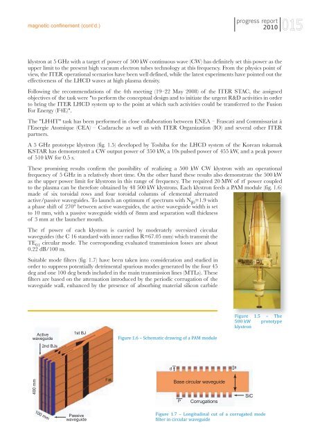
A 5 GHz prototype klystron (fig. 1.5) developed by Toshiba for the LHCD system of the Korean tokamak<br />
KSTAR has demonstrated a CW output power of 350 kW, a 10s pulsed power of 455 kW, and a peak power<br />
of 510 kW for 0.5 s.<br />
These promising results confirm the possibility of realizing a 500 kW CW klystron with an operational<br />
frequency of 5 GHz in a relatively short time. On the other hand these results also demonstrate the 500 kW<br />
as the upper power limit for klystrons in this range of frequency. The required 20 MW of rf power coupled<br />
to the plasma can be therefore obtained by 48 500 kW klystrons. Each klystron feeds a PAM module (fig. 1.6)<br />
made of six toroidal rows and four toroidal columns of elemental alternated<br />
active/passive waveguides. To launch an optimum rf spectrum with N 0<br />
=1.9 with<br />
a phase shift of 270° between active waveguides, the active waveguide width is set<br />
to 10 mm, with a passive waveguide width of 8mm and separation wall thickness<br />
of 3 mm at the launcher mouth.<br />
The rf power of each klystron is carried by moderately oversized circular<br />
waveguides (the C 16 standard with inner ra<strong>di</strong>us R=67.05 mm) which transmit the<br />
TE 01<br />
circular mode. The correspon<strong>di</strong>ng evaluated transmission losses are about<br />
0.22 dB/100 m.<br />
Suitable mode filters (fig. 1.7) have been taken into consideration and stu<strong>di</strong>ed in<br />
order to suppress potentially detrimental spurious modes generated by the four 45<br />
deg and one 100 deg bends included in the main transmission lines (MTLs). These<br />
filters are based on the attenuation introduced by the perio<strong>di</strong>c corrugation of the<br />
waveguide wall, enhanced by the presence of absorbing material silicon carbide<br />
Active<br />
waveguide<br />
1st BJ<br />
Figure 1.6 – Schematic drawing of a PAM module<br />
Figure 1.5 – The<br />
500 kW prototype<br />
klystron<br />
2nd BJs<br />
d<br />
a<br />
400 mm<br />
Base circular waveguide<br />
P<br />
Corrugations<br />
SiC<br />
100 mm<br />
Passive<br />
waveguide<br />
Figure 1.7 – Longitu<strong>di</strong>nal cut of a corrugated mode<br />
filter in circular waveguide


