

Prime pagine RA2010FUS:Copia di Layout 1 - ENEA - Fusione
Prime pagine RA2010FUS:Copia di Layout 1 - ENEA - Fusione
Prime pagine RA2010FUS:Copia di Layout 1 - ENEA - Fusione

You also want an ePaper? Increase the reach of your titles
YUMPU automatically turns print PDFs into web optimized ePapers that Google loves.
magnetic confinement (cont’d.)<br />
progress report<br />
2010<br />
039<br />
<strong>ENEA</strong> Frascati scientists have participated in the analysis of the data gathered during the last campaigns and<br />
finalized journal papers and contribution to international conferences, such as EPS, SOFT, IAEA and others.<br />
On the basis of data taken during the last experimental campaigns, significant progress was made in terms of<br />
analysis, interpretation and <strong>di</strong>agnostic commissioning. Highlights regar<strong>di</strong>ng the main areas of interest are<br />
reported below.<br />
Pellet stu<strong>di</strong>es<br />
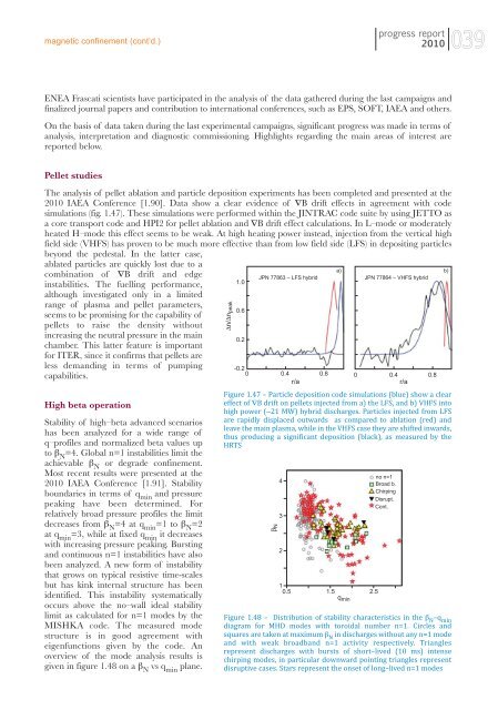
The analysis of pellet ablation and particle deposition experiments has been completed and presented at the<br />
2010 IAEA Conference [1.90]. Data show a clear evidence of ∇B drift effects in agreement with code<br />
simulations (fig. 1.47). These simulations were performed within the JINTRAC code suite by using JETTO as<br />
a core transport code and HPI2 for pellet ablation and ∇B drift effect calculations. In L–mode or moderately<br />
heated H–mode this effect seems to be weak. At high heating power instead, injection from the vertical high<br />
field side (VHFS) has proven to be much more effective than from low field side (LFS) in depositing particles<br />
beyond the pedestal. In the latter case,<br />
ablated particles are quickly lost due to a<br />
combination of ∇B drift and edge<br />
instabilities. The fuelling performance,<br />
although investigated only in a limited<br />
range of plasma and pellet parameters,<br />
seems to be promising for the capability of<br />
pellets to raise the density without<br />
increasing the neutral pressure in the main<br />
chamber. This latter feature is important<br />
for ITER, since it confirms that pellets are<br />
less deman<strong>di</strong>ng in terms of pumping<br />
capabilities.<br />
High beta operation<br />
Stability of high–beta advanced scenarios<br />
has been analyzed for a wide range of<br />
q–profiles and normalized beta values up<br />
to β N<br />
=4. Global n=1 instabilities limit the<br />
achievable β N<br />
or degrade confinement.<br />
Most recent results were presented at the<br />
2010 IAEA Conference [1.91]. Stability<br />
boundaries in terms of q min<br />
and pressure<br />
peaking have been determined. For<br />
relatively broad pressure profiles the limit<br />
decreases from β N<br />
=4 at q min<br />
=1 to β N<br />
=2<br />
at q min<br />
=3, while at fixed q min<br />
it decreases<br />
with increasing pressure peaking. Bursting<br />
and continuous n=1 instabilities have also<br />
been analyzed. A new form of instability<br />
that grows on typical resistive time-scales<br />
but has kink internal structure has been<br />
identified. This instability systematically<br />
occurs above the no–wall ideal stability<br />
limit as calculated for n=1 modes by the<br />
MISHKA code. The measured mode<br />
structure is in good agreement with<br />
eigenfunctions given by the code. An<br />
overview of the mode analysis results is<br />
given in figure 1.48 on a β N<br />
vs q min<br />
plane.<br />
Δn/Δn peak<br />
1.0<br />
0.6<br />
0.2<br />
JPN 77863 – LFS hybrid<br />
-0.2<br />
0 0.4<br />
r/a<br />
a) b)<br />
JPN 77864 – VHFS hybrid<br />
0.8 0 0.4 0.8<br />
r/a<br />
Figure 1.47 – Particle deposition code simulations (blue) show a clear<br />
effect of ∇B drift on pellets injected from a) the LFS, and b) VHFS into<br />
high power (∼21 MW) hybrid <strong>di</strong>scharges. Particles injected from LFS<br />
are rapidly <strong>di</strong>splaced outwards as compared to ablation (red) and<br />
leave the main plasma, while in the VHFS case they are shifted inwards,<br />
thus producing a significant deposition (black), as measured by the<br />
HRTS<br />
βN<br />
4<br />
3<br />
2<br />
1<br />
0.5 1.5 2.5<br />
q min<br />
no n=1<br />
Broad b.<br />
Chirping<br />
Disrupt.<br />
Cont.<br />
Figure 1.48 – Distribution of stability characteristics in the β N –q min<br />
<strong>di</strong>agram for MHD modes with toroidal number n=1. Circles and<br />
squares are taken at maximum β N in <strong>di</strong>scharges without any n=1 mode<br />
and with weak broadband n=1 activity respectively. Triangles<br />
represent <strong>di</strong>scharges with bursts of short–lived (10 ms) intense<br />
chirping modes, in particular downward pointing triangles represent<br />
<strong>di</strong>sruptive cases. Stars represent the onset of long–lived n=1 modes


