0870 849 8057 USERS G 24, 30 - Ideal Heating
0870 849 8057 USERS G 24, 30 - Ideal Heating
0870 849 8057 USERS G 24, 30 - Ideal Heating

Create successful ePaper yourself
Turn your PDF publications into a flip-book with our unique Google optimized e-Paper software.
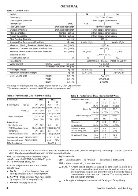
Table 1 - general Data<br />
gENERaL<br />
i-mini <strong>24</strong> <strong>30</strong><br />
Gas supply 2H - G20 - 20mbar<br />
Gas Supply Connection 15mm copper compression<br />
Injector Size (mm) 4.15 4.65<br />
Inlet Connection Domestic Hot Water 15mm copper tail<br />
Outlet Connection Domestic Hot Water 15mm copper compression<br />
Flow Connection Central <strong>Heating</strong> 22mm copper compression<br />
Return Connection Central <strong>Heating</strong> 22mm copper compression<br />
Flue Terminal Diameter mm (in) 100 (4)<br />
Average Flue Temp-Mass Flow Rate (DHW) 63 o C - 11g/s 68 o C - 13g/s<br />
Maximum Working Pressure (Sealed Systems) bar (lb/in 2 ) 2.5 (36.3)<br />
Maximum Domestic Hot Water Inlet Pressure bar (lb/in 2 ) 10.0 (145)<br />
Minimum Domestic Hot Water Inlet Pressure* bar (lb/in 2 ) 0.8 (11.6) 1.3 (18.9)<br />
Electrical Supply 2<strong>30</strong> V ~ 50 Hz.<br />
Power Consumption W 146 152<br />
Fuse Rating External : 3A Internal : T4H HRC L250 V<br />
Water content Central <strong>Heating</strong> litre (gal) 1.2 (0.26)<br />
Domestic Hot Water litre (gal) 0.5 (0.11)<br />
Packaged Weight kg (lb) 37.2 (82.0) 37.3 (82.2)<br />
Maximum Installation Weight kg (lb) 32.7 (72.1) 32.8 (72.3)<br />
Boiler Casing Size Height mm (in) 700 (27.5)<br />
Width mm (in) 395 (15.5)<br />
Depth mm (in) 278 (11)<br />
*Required for maximum flow rate. Boiler operates down to 2 l/min DHW delivery<br />
** In areas of low water pressure the DHW restrictor can be removed<br />
Maximum DHW Input : <strong>24</strong> <strong>30</strong><br />
Nett CV kW <strong>24</strong>.3 <strong>30</strong>.4<br />
Gross CV<br />
(Btu/h)<br />
kW<br />
(Btu/h)<br />
(82,900)<br />
27.0<br />
(92,000)<br />
(103,600)<br />
33.7<br />
(115,000)<br />
Gas Consumption l/s 0.698 0.871<br />
(ft3 Boiler Input : Max. Min.<br />
<strong>24</strong> <strong>30</strong><br />
Boiler Input ‘Q’ Nett CV<br />
Gross CV<br />
kW <strong>24</strong>.3 4.9 6.1<br />
(Btu/h) (82,900) (16,600 (20,700<br />
kW 27.0 5.4 6.7<br />
(Btu/h) (92,000) (18,400) (23,000)<br />
Gas Consumption l/s 0.698 0.139 0.173<br />
(ft /h) (89) (111)<br />
Maximum kW <strong>24</strong>.2 <strong>30</strong>.3<br />
DHW Output (Btu/h) (82,600) (103,<strong>30</strong>0)<br />
DHW Flow Rate l/min 9.9 12.4<br />
at 35°C temp. rise. (gpm) (2.2) (2.8)<br />
DHW Specific Rate l/min 11.5 14.5<br />
(gpm) (2.5) (3.2)<br />
3 /h) (89) (17.8) (22)<br />
Boiler Output :<br />
Non Condensing kW <strong>24</strong>.2 4.8 6.1<br />
70oC Mean Water temp. (Btu/h) (82,600) (16,500) (20,700)<br />
Condensing kW 25.6 5.1 6.4<br />
40o Table 2 - performance Data - Central heating Table 3 - performance Data - Domestic hot Water<br />
C Mean Water temp. (Btu/h) (87,400) (17,500) (21,800)<br />
Seasonal efficiency* SEDBUK 2005 91% 91.1%<br />
Seasonal efficiency* SEDBUK 2009 89% 89%<br />
NOx Classification CLASS 5<br />
Note. Gas consumption is calculated using a<br />
calorific value of 38.7 MJ/m3 (1038 Btu/ft3 ) gross<br />
or 34.9 MJ/m3 (935 Btu/ft3 ) nett<br />
To obtain the gas consumption at a different<br />
calorific value:<br />
a. For l/s - divide the gross heat input<br />
(kW) by the gross C.V. of the gas (MJ/m3 )<br />
b. For ft3 /h - divide the gross heat input (Btu/h)<br />
by the gross C.V. of the gas (Btu/ft3 )<br />
c. For m3 * The value is used in the UK Government’s Standard Assessment Procedure (SAP) for energy rating of dwellings. The test data from<br />
which it has been calculated have been certified by a notified body.<br />
Key to symbols<br />
gB = United Kingdom IE = Ireland (Countries of destination)<br />
pMs = Maximum operating pressure of water<br />
C C C = A room sealed appliance designed for connection via ducts to a<br />
13 33 53<br />
horizontal or vertical terminal, which admits fresh air to the burner<br />
and discharges the products of combustion to the outside through<br />
orifices which, in this case, are concentric. The fan is up stream of<br />
the combustion chamber.<br />
/h - multiply l/s by 3.6.<br />
I2h = An appliance designed for use on 2nd Family gas, Group H only.<br />
4 i-mini - Installation and Servicing