0870 849 8057 USERS G 24, 30 - Ideal Heating
0870 849 8057 USERS G 24, 30 - Ideal Heating
0870 849 8057 USERS G 24, 30 - Ideal Heating

Create successful ePaper yourself
Turn your PDF publications into a flip-book with our unique Google optimized e-Paper software.
FaULT FINDINg FaULT FINDINg FaULT FINDINg FaULT FINDINg FaULT FINDINg<br />
54<br />
FaULT FINDINg<br />
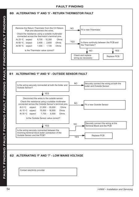
80 aLTERNaTINg ‘F’ aND ‘5’ - RETURN ThERMIsTOR FaULT<br />
Remove the Return Thermistor from the CH Return<br />
Pipe and disconnect the wires.<br />
Check the resistance using a suitable multimeter<br />
connected across the thermistor’s terminal pins.<br />
At 25 o C expect 9,700 - 10,<strong>30</strong>0 Ohms<br />
At 60 o C expect 2,400 - 2,600 Ohms<br />
At 85 o C expect 1,000 - 1,100 Ohms<br />
Is the Thermistor value correct?<br />
NO<br />
YES<br />
Fit a new Thermistor<br />
Is there continuity between the PCB and<br />
the Thermistor?<br />
Check and replace<br />
wiring as necessary<br />
81 aLTERNaTINg ‘F’ aND ‘6’ - OUTsIDE sENsOR FaULT<br />
Is the wiring securely connected at both the boiler and<br />
Outside Sensor?<br />
YES<br />
Disconnect the wires to the outside sensor.<br />
Check the resistance using a suitable multimeter<br />
connected across the Outside Sensor’s terminal pins.<br />
At 0 oC expect 31,000 - 35,000 Ohms<br />
At 15 oC expect 15,000 - 16,500 Ohms<br />
At <strong>30</strong> oC expect 7,700 - 8,500 Ohms<br />
Is the Outside Sensor value correct?<br />
YES<br />
NO YES<br />
Fit a new Outside Sensor<br />
Is the wiring securely connected between the<br />
incoming terminal block boiler connection of the<br />
Outside Sensor and the PCB?<br />
YES<br />
Replace PCB<br />
82 aLTERNaTINg ‘F’ aND ‘7’ - LOW MaINs VOLTagE<br />
Contact electricity provider<br />
NO<br />
Replace PCB<br />
NO Securely connect the wiring at both the<br />
boiler and Outside Sensor<br />
NO<br />
Securely connect the wiring at the<br />
Terminal Block and the PCB<br />
i-mini - Installation and Servicing