0870 849 8057 USERS G 24, 30 - Ideal Heating
0870 849 8057 USERS G 24, 30 - Ideal Heating
0870 849 8057 USERS G 24, 30 - Ideal Heating

Create successful ePaper yourself
Turn your PDF publications into a flip-book with our unique Google optimized e-Paper software.
gas sUppLy<br />
The local gas supplier should be consulted, at the installation<br />
planning stage, in order to establish the availability of an adequate<br />
supply of gas. An existing service pipe must NOT be used without<br />
prior consultation with the local gas supplier.<br />
The boiler MUST be installed on a gas supply with a governed<br />
meter only.<br />
A gas meter can only be connected by the local gas supplier or<br />
by a Gas Safe Registered Engineer. In IE by a Registered Gas<br />
Installer (RGII).<br />
An existing meter should be checked, preferably by the gas<br />
supplier, to ensure that the meter is adequate to deal with the rate<br />
of gas supply required.<br />
It is the responsibility of the Gas Installer to size the gas<br />
Installer to size the gas installation pipework in accordance with<br />
BS6891:2005. Whilst the principle of the 1:1 gas valve ensures<br />
the i-mini range is able to deliver it’s full output at inlet pressures<br />
as low as 14mb, other gas appliances in the property may not be<br />
as tolerant. When operating pressures are found to be below the<br />
minimum meter outlet of 19mb these should be checked to ensure<br />
this is adequate for correct and safe operation.<br />
Allowing for the acceptable pressure loss of 1mb across the<br />
installation pipework, it can be assumed that a minimum permitted<br />
operating pressure of 18mb will be delivered to the inlet of<br />
the appliance. (Reference BS 6400-1 Clause 6.2 Pressure<br />
Absorption).<br />
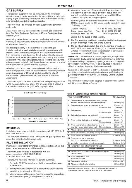
The external gas cock could further reduce the operating pressure<br />
when measured at its test point. The pressure drop is relative to<br />
the heat input to the boiler (kW), refer to graph below.<br />
IMpORTaNT.<br />
Installation pipes must be fitted in accordance with BS.6891. In IE<br />
refer to IS.813:2002.<br />
The complete installation MUST be tested for gas tightness and<br />
purged as described in the above code.<br />
FLUE INsTaLLaTION<br />
Pluming will occur at the terminal so terminal positions where this<br />
could cause a nuisance should be avoided.<br />
The flue must be installed in accordance with the<br />
recommendations of BS. 5440-1: 2008.<br />
In IE refer to I.S. 813:2002.<br />
The following notes are intended for general guidance:<br />
1. The boiler MUST be installed so that the terminal is exposed<br />
to external air.<br />
2. It is important that the position of the terminal allows the free<br />
passage of air across it at all times.<br />
3. Minimum acceptable spacing from the terminal to obstructions<br />
and ventilation openings are specified in Table 4.<br />
gENERaL<br />
4. Where the lowest part of the terminal is fitted less than 2m<br />
(6’6”) above a balcony, above ground or above a flat roof<br />
to which people have access then the terminal MUST be<br />
protected by a purpose designed guard.<br />
Terminal guards are available from boiler suppliers. (Ask for<br />
TFC flue guard model no. K6 - round, plastic coated). In case<br />
of difficulty contact:<br />
Grasslin (UK) Ltd. Tel. + 44 (0) 01732 359 888<br />
Tower House, Vale Rise Fax. + 44 (0) 01732 354 445<br />
Tonbridge. Kent TN9 1TB www.tfc-group.co.uk<br />
Ensure that the guard is fitted centrally.<br />
5. The flue assembly shall be so placed or shielded as to prevent<br />
ignition or damage to any part of any building.<br />
6. The air inlet/products outlet duct and the terminal of the boiler<br />
MUST NOT be closer than 25mm (1”) to combustible material.<br />
Detailed recommendations on the protection of combustible<br />
material are given in BS. 5440-1:2008.<br />
IMpORTaNT. It is essential to ensure, in practice, that products<br />
of combustion discharging from the terminal cannot re-enter the<br />
building or buildings through any openings into the building such<br />
as ventilators, windows, doors, or other sources of natural air<br />
infiltration, such as forced ventilation openings etc.<br />
If products of combustion re-entry is identified or suspected this<br />
should be immediately investigated and corrected following the<br />
guidance provided in the current Gas Industry Unsafe Situation<br />
Procedure.<br />
The terminal assembly can be adapted to accommodate various<br />
wall thicknesses. Refer to Frame 11.<br />
Table 4 - Balanced Flue Terminal position<br />
Flue Terminal positions Min. spacing*<br />
1. Directly below, above or alongside an opening<br />
window, air vent or other ventilation opening. <strong>30</strong>0mm (12”)<br />
2. Below guttering, drain pipes or soil pipes. 25mm ( 1”)*<br />
BS5440-1 2008 75mm (3”)<br />
3. Below eaves. 25mm (1”)*<br />
BS5440-1 2008 200mm (8”)<br />
4. Below balconies or a car port roof. 25mm (1”)*<br />
BS5440-1 2008 200mm (8”)<br />
5. From vertical drain pipes or soil pipes. 25mm (1”)*<br />
BS5440-1 2008 150mm (6”)<br />
6. From an internal or external corner or to a 25mm (1”)*<br />
boundary along side the terminal. BS5440-1 2008 <strong>30</strong>0mm (12”)<br />
7. Above adjacent ground, roof or balcony level. <strong>30</strong>0mm (12”)<br />
8. From a surface or a boundary facing the terminal. 600mm (<strong>24</strong>”)<br />
9. From a terminal facing a terminal. 1,200mm (48”)<br />
10. From an opening in a car port<br />
(e.g. door or window) into dwelling. 1,200mm (48”)<br />
11. Vertically from a terminal on the same wall. 1,500mm (60”)<br />
12. Horizontally from a terminal on the wall.<br />
Vertical Terminals<br />
<strong>30</strong>0mm (12”)<br />
13. Above the roof pitch with roof slope of all angles. <strong>30</strong>0mm (12”)<br />
Above flat roof. <strong>30</strong>0mm (12”)<br />
14. From a single wall face. <strong>30</strong>0mm (12”)<br />
From corner walls. <strong>30</strong>0mm (12”)<br />
15. Below velux window 2000mm (79”)<br />
16. Above or side of velux window 600mm (<strong>24</strong>”)<br />
* Only one reduction down to 25mm is allowable per installation<br />
otherwise BS5440-1 2008 dimensions must be followed.<br />
8 i-mini - Installation and Servicing