0870 849 8057 USERS G 24, 30 - Ideal Heating
0870 849 8057 USERS G 24, 30 - Ideal Heating
0870 849 8057 USERS G 24, 30 - Ideal Heating

Create successful ePaper yourself
Turn your PDF publications into a flip-book with our unique Google optimized e-Paper software.
sERVICINg<br />
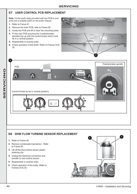
Note. Fit the earth strap provided with the PCB to your<br />
wrist and a suitable earth on the boiler chassis.<br />
1. Refer to Frame 47.<br />
2. Remove the main PCB, refer to Frame 56.<br />
3. Unclip the PCB and lift to clear the mounting posts.<br />
4. Fit the new PCB ensuring the 4 potentiometer<br />
spindles line up with the control knobs which must<br />
be in a vertical position.<br />
5. Reassemble in reverse order.<br />
6. Check operation of the boiler. Refer to Frames 34 &<br />
35.<br />
44<br />
57 UsER CONTROL pCB REpLaCEMENT<br />
4<br />
PCB<br />
Control Knobs (to be in vertical position)<br />
sERVICINg<br />
58 DhW FLOW TURBINE sENsOR REpLaCEMENT<br />
1. Refer to Frame 45.<br />
2. Remove condensate trap/siphon. Refer<br />
to Frame 55.<br />
3. Lift off the flow turbine sensor plastic<br />
retaining clip.<br />
4. Unplug the electrical connection and<br />
transfer to new turbine sensor.<br />
5. Reassemble in reverse order.<br />
6. Check operation of the boiler. Refer to<br />
Frames 34 & 35.<br />
4<br />
3<br />
Potentiometer spindle<br />
i-mini - Installation and Servicing<br />
3