R4300i Product Information - MIPS Technologies, Inc.
R4300i Product Information - MIPS Technologies, Inc.
R4300i Product Information - MIPS Technologies, Inc.

Create successful ePaper yourself
Turn your PDF publications into a flip-book with our unique Google optimized e-Paper software.
<strong>R4300i</strong> MICROPROCESSOR<br />
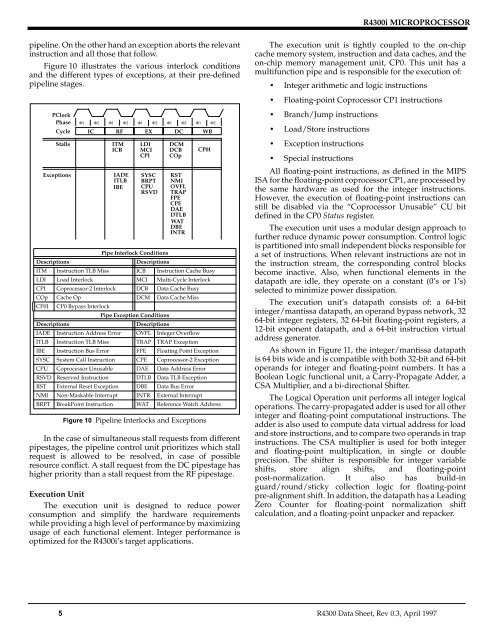
pipeline. On the other hand an exception aborts the relevant<br />
instruction and all those that follow.<br />
Figure 10 illustrates the various interlock conditions<br />
and the different types of exceptions, at their pre-defined<br />
pipeline stages.<br />
The execution unit is tightly coupled to the on-chip<br />
cache memory system, instruction and data caches, and the<br />
on-chip memory management unit, CP0. This unit has a<br />
multifunction pipe and is responsible for the execution of:<br />
• Integer arithmetic and logic instructions<br />
• Floating-point Coprocessor CP1 instructions<br />
PClock<br />
Phase<br />
Cycle<br />
Stalls<br />
Exceptions<br />
Φ1 Φ2 Φ1 Φ2 Φ1 Φ2 Φ1 Φ2 Φ1 Φ2<br />
IC RF EX DC WB<br />
ITM<br />
ICB<br />
IADE<br />
ITLB<br />
IBE<br />
LDI<br />
MCI<br />
CPI<br />
SYSC<br />
BRPT<br />
CPU<br />
RSVD<br />
DCM<br />
DCB<br />
COp<br />
RST<br />
NMI<br />
OVFL<br />
TRAP<br />
FPE<br />
CPE<br />
DAE<br />
DTLB<br />
WAT<br />
DBE<br />
INTR<br />
CP0I<br />
Pipe Interlock Conditions<br />
Descriptions<br />
Descriptions<br />
ITM Instruction TLB Miss ICB Instruction Cache Busy<br />
LDI Load Interlock MCI Multi-Cycle Interlock<br />
CPI Coprocessor-2 Interlock DCB Data Cache Busy<br />
COp Cache Op DCM Data Cache Miss<br />
CP0I CP0 Bypass Interlock<br />
Pipe Exception Conditions<br />
Descriptions<br />
Descriptions<br />
IADE Instruction Address Error OVFL Integer Overflow<br />
ITLB Instruction TLB Miss TRAP TRAP Exception<br />
IBE Instruction Bus Error FPE Floating Point Exception<br />
SYSC System Call Instruction CPE Coprocessor-2 Exception<br />
CPU Coprocessor Unusable DAE Data Address Error<br />
RSVD Reserved Instruction DTLB Data TLB Exception<br />
RST External Reset Exception DBE Data Bus Error<br />
NMI Non-Maskable Interrupt INTR External Interrupt<br />
BRPT BreakPoint Instruction WAT Reference Watch Address<br />
Figure 10 Pipeline Interlocks and Exceptions<br />
In the case of simultaneous stall requests from different<br />
pipestages, the pipeline control unit prioritizes which stall<br />
request is allowed to be resolved, in case of possible<br />
resource conflict. A stall request from the DC pipestage has<br />
higher priority than a stall request from the RF pipestage.<br />
Execution Unit<br />
The execution unit is designed to reduce power<br />
consumption and simplify the hardware requirements<br />
while providing a high level of performance by maximizing<br />
usage of each functional element. Integer performance is<br />
optimized for the <strong>R4300i</strong>’s target applications.<br />
• Branch/Jump instructions<br />
• Load/Store instructions<br />
• Exception instructions<br />
• Special instructions<br />
All floating-point instructions, as defined in the <strong>MIPS</strong><br />
ISA for the floating-point coprocessor CP1, are processed by<br />
the same hardware as used for the integer instructions.<br />
However, the execution of floating-point instructions can<br />
still be disabled via the “Coprocessor Unusable” CU bit<br />
defined in the CP0 Status register.<br />
The execution unit uses a modular design approach to<br />
further reduce dynamic power consumption. Control logic<br />
is partitioned into small independent blocks responsible for<br />
a set of instructions. When relevant instructions are not in<br />
the instruction stream, the corresponding control blocks<br />
become inactive. Also, when functional elements in the<br />
datapath are idle, they operate on a constant (0’s or 1’s)<br />
selected to minimize power dissipation.<br />
The execution unit’s datapath consists of: a 64-bit<br />
integer/mantissa datapath, an operand bypass network, 32<br />
64-bit integer registers, 32 64-bit floating-point registers, a<br />
12-bit exponent datapath, and a 64-bit instruction virtual<br />
address generator.<br />
As shown in Figure 11, the integer/mantissa datapath<br />
is 64 bits wide and is compatible with both 32-bit and 64-bit<br />
operands for integer and floating-point numbers. It has a<br />
Boolean Logic functional unit, a Carry-Propagate Adder, a<br />
CSA Multiplier, and a bi-directional Shifter.<br />
The Logical Operation unit performs all integer logical<br />
operations. The carry-propagated adder is used for all other<br />
integer and floating-point computational instructions. The<br />
adder is also used to compute data virtual address for load<br />
and store instructions, and to compare two operands in trap<br />
instructions. The CSA multiplier is used for both integer<br />
and floating-point multiplication, in single or double<br />
precision. The shifter is responsible for integer variable<br />
shifts, store align shifts, and floating-point<br />
post-normalization. It also has build-in<br />
guard/round/sticky collection logic for floating-point<br />
pre-alignment shift. In addition, the datapath has a Leading<br />
Zero Counter for floating-point normalization shift<br />
calculation, and a floating-point unpacker and repacker.<br />
5 R4300 Data Sheet, Rev 0.3, April 1997