AVR 255/AVR 355 Audio/VideoReceiver - Harman Kardon
AVR 255/AVR 355 Audio/VideoReceiver - Harman Kardon
AVR 255/AVR 355 Audio/VideoReceiver - Harman Kardon

Create successful ePaper yourself
Turn your PDF publications into a flip-book with our unique Google optimized e-Paper software.
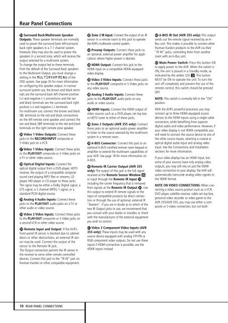
Rear Panel Connections<br />
Surround Back/Multiroom Speaker<br />
Outputs: These speaker terminals are normally<br />
used to power the surround back left/surround<br />
back right speakers in a 7.1 channel system.<br />
However, they may also be used to power the<br />
speakers in a second zone, which will receive the<br />
output selected for a multiroom system.<br />
To change the output fed to these terminals<br />
from the default of the Surround Back speakers<br />
to the Multiroom Output, you must change a<br />
setting in the MULTIROOM MENU of the<br />
OSD system. See page 35 for more information<br />
on configuring this speaker output. In normal<br />
surround system use, the brown and black terminals<br />
are the surround back left channel positive<br />
(+) and negative (–) connections and the tan<br />
and black terminals are the surround back right<br />
positive (+) and negative (–) terminals.<br />
For multiroom use, connect the brown and black<br />
SBL terminals to the red and black connections<br />
on the left remote zone speaker and connect the<br />
tan and black SBR terminals to the red and black<br />
terminals on the right remote zone speaker.<br />
Video 1 Video Outputs: Connect these<br />
jacks to the RECORD/INPUT composite or<br />
S-Video jack on a VCR.<br />
Video 1 Video Inputs: Connect these jacks<br />
to the PLAY/OUT composite or S-Video jacks on<br />
a TV or other video source.<br />
Optical Digital Inputs: Connect the<br />
optical digital output from a DVD player, HDTV<br />
receiver, the output of a compatible computer<br />
sound card playing MP3 files or streams, LD<br />
player, MD player or CD player to these jacks.<br />
The signal may be either a Dolby Digital signal, a<br />
DTS signal, a 2 channel MPEG 1 signal, or a<br />
standard PCM digital source.<br />
Analog 4 <strong>Audio</strong> Inputs: Connect these<br />
jacks to the PLAY/OUT audio jacks on a TV or<br />
other audio or video source.<br />
Video 2 Video Inputs: Connect these jacks<br />
to the PLAY/OUT composite or S-Video jacks on<br />
a second VCR or other video source.<br />
Remote Input and Output: If the <strong>AVR</strong>’s<br />
front-panel IR sensor is blocked due to cabinet<br />
doors or other obstructions, an external IR sensor<br />
may be used. Connect the output of the<br />
sensor to the Remote IN jack.<br />
The Output connection permits the IR sensor in<br />
the receiver to serve other remote controlled<br />
devices. Connect this jack to the “IR IN” jack on<br />
<strong>Harman</strong> <strong>Kardon</strong> or other compatible equipment.<br />
Zone 2 IR Input: Connect the output of an IR<br />
sensor in a remote room to this jack to operate<br />
the <strong>AVR</strong>’s multiroom control system.<br />
Preamp Outputs: Connect these jacks to<br />
an optional, external power amplifier for applications<br />
where higher power is desired.<br />
HDMI Output: Connect this jack to the<br />
HDMI input on a compatible HDMI-equipped<br />
video display.<br />
Video 3 Video Inputs: Connect these jacks<br />
to the PLAY/OUT composite or S-Video jacks on<br />
any video source.<br />
Analog 3 <strong>Audio</strong> Inputs: Connect these<br />
jacks to the PLAY/OUT audio jacks on any<br />
audio or video source.<br />
HDMI Inputs: Connect the HDMI output of<br />
video sources such as a DVD player, set-top box<br />
or HDTV tuner to either of these jacks.<br />
Zone 2 Outputs (<strong>AVR</strong> <strong>355</strong> only): Connect<br />
these jacks to an optional audio power amplifier<br />
to listen to the source selected by the multiroom<br />
system in a remote room.<br />
A-BUS Connector: Connect this jack to an<br />
optional A-BUS-certified remote room keypad or<br />
amplifier to extend the multiroom capabilities of<br />
your <strong>AVR</strong>. See page 18 for more information on<br />
A-BUS.<br />
Remote IR Carrier Output (<strong>AVR</strong> <strong>355</strong><br />
only): The output of this jack is the full signal<br />
received at the Remote Sensor Window Ó<br />
or input through the Remote IR Input <br />
including the carrier frequency that is removed<br />
from signals at the Remote IR Output . Use<br />
this output to extend IR remote signals to the<br />
input of compatible products by direct connection<br />
or through the use of optional, external IR<br />
“blasters”. If you are in doubt as to which of the<br />
two IR Output jacks to use, we recommend that<br />
you consult with your dealer or installer, or check<br />
with the manufacturer of the external equipment<br />
you wish to control.<br />
Video 3 Component Video Inputs (<strong>AVR</strong><br />
<strong>355</strong> only): These inputs may be used with any<br />
source device equipped with analog Y/Pr/Pb or<br />
RGB component video outputs. Do not use these<br />
inputs if HDMI connection is possible, use the<br />
HDMI inputs instead.<br />
A-BUS IR Out (<strong>AVR</strong> <strong>355</strong> only): This output<br />
sends out the remote signal received by an A-<br />
Bus unit. This makes it possible to connect other<br />
<strong>Harman</strong> <strong>Kardon</strong> products to the <strong>AVR</strong> via their<br />
"IR IN" jacks, controlling them from another<br />
room with an A-Bus unit.<br />
Main Power Switch: Press this button ON<br />
to apply power to the <strong>AVR</strong>. When the switch is<br />
ON, the unit is placed in a Standby mode, as<br />
indicated by the amber LED 3. This button<br />
MUST be ON to operate the unit. To turn the<br />
unit off completely and prevent the use of the<br />
remote control, this switch should be pressed<br />
OFF.<br />
NOTE: This switch is normally left in the “ON”<br />
position.<br />
With the <strong>AVR</strong>’s powerful processor, you may<br />
connect up to three HDMI-equipped source<br />
devices to the HDMI inputs using a single-cable<br />
connection, while benefiting from superior<br />
digital audio and video performance. However, if<br />
your video display is not HDMI-compatible, you<br />
will need to connect the source device to one of<br />
the other source inputs, selecting a coaxial or<br />
optical digital audio input and analog video<br />
input. See the Connections and Installation<br />
sections for more information.<br />
If your video display has an HDMI input, but<br />
some of your sources have only analog video<br />
outputs, you may still rely on just the HDMI<br />
video connection to your display; the <strong>AVR</strong> will<br />
automatically transcode analog video signals to<br />
the HDMI format.<br />
NOTE ON VIDEO CONNECTIONS: When connecting<br />
a video source product such as a VCR,<br />
DVD player, satellite receiver, cable set-top box,<br />
personal video recorder or video game to the<br />
<strong>AVR</strong> <strong>255</strong>/<strong>AVR</strong> <strong>355</strong>, you may use either a composite<br />
or S-video connection, but not both.<br />
10 REAR PANEL CONNECTIONS