AVR 255/AVR 355 Audio/VideoReceiver - Harman Kardon
AVR 255/AVR 355 Audio/VideoReceiver - Harman Kardon
AVR 255/AVR 355 Audio/VideoReceiver - Harman Kardon

Create successful ePaper yourself
Turn your PDF publications into a flip-book with our unique Google optimized e-Paper software.
ENGLISH<br />
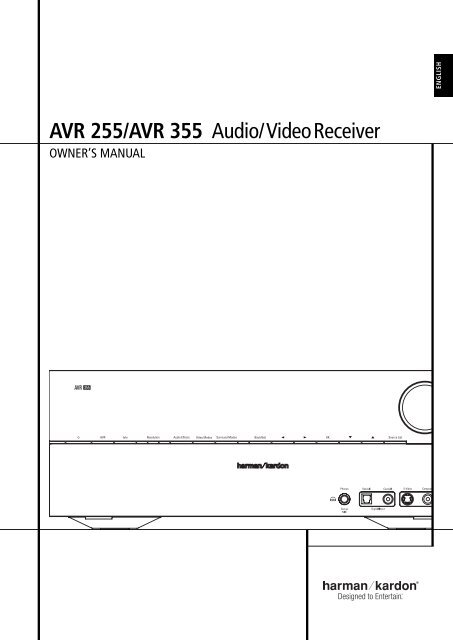
<strong>AVR</strong> <strong>255</strong>/<strong>AVR</strong> <strong>355</strong> <strong>Audio</strong>/<strong>VideoReceiver</strong><br />
OWNER’S MANUAL<br />
<strong>AVR</strong> Info Resolution <strong>Audio</strong> Effects Video Modes Surround Modes Back/Exit A B OK<br />
L K Source List<br />
Composit
Table of Contents<br />
3 Introduction<br />
4 Safety Information<br />
5 Unpacking<br />
6 Front Panel Controls<br />
8 Rear Panel Connections<br />
11 Main Remote Control Functions<br />
13 Zone 2 Remote Control Functions<br />
15 Installation and Connections<br />
15 <strong>Audio</strong> Equipment Connections<br />
15 HDMI Input Connections<br />
15 HDMI Output Connections<br />
16 Analog and Digital Input Connections<br />
17 Video Equipment Connections<br />
18 System and Power Connections<br />
18 Main Room Remote Control Extension<br />
18 Zone 2 IR Link<br />
18 Multiroom <strong>Audio</strong> Connection<br />
18 A-BUS Installation Connections<br />
19 Speaker Selection<br />
19 Speaker Placement<br />
20 System Configuration<br />
20 First Turn On<br />
20 Using the On-Screen Display<br />
20 System Setup<br />
20 Source Selection<br />
21 <strong>Audio</strong> and Video Input Selection<br />
21 Set Up Sources<br />
21 <strong>Audio</strong> Effects<br />
21 Video Mode<br />
21 Surround Mode<br />
21 <strong>Audio</strong> Format From Source<br />
21 Video Input From Source<br />
21 <strong>Audio</strong> Input From Source<br />
21 Resolution To Display<br />
22 Resolution From Source<br />
22 Adjust Lip Sync<br />
22 Change Source Name<br />
22 Zone 2 <strong>Audio</strong><br />
22 Speaker Setup, EzSet/EQ<br />
22 Speaker Setup, Manual<br />
28 Operation<br />
28 Surround Mode Chart<br />
30 Basic Operation<br />
30 Mute Function<br />
30 <strong>Audio</strong> Effects<br />
30 Video Modes<br />
30 Source Selection<br />
30 Video Input Selection<br />
31 Video Troubleshooting Tips<br />
31 Multichannel Disc Players with/without<br />
HDMI<br />
31 6/8-Channel Direct Input<br />
31 Controls and Use of Headphones<br />
31 Surround Mode Selection<br />
32 Digital <strong>Audio</strong> Signals<br />
33 Surround modes<br />
34 Tape Recording<br />
34 The Bridge<br />
35 Multiroom Operation<br />
35 Multiroom Setup<br />
35 Surround Amplifier Channel Assignment<br />
37 Video Adjustments<br />
37 Video Modes<br />
38 <strong>Audio</strong> Adjustments<br />
38 <strong>Audio</strong> Effects<br />
38 Advanced Features<br />
38 System Settings<br />
38 Front Panel Dimmer<br />
38 Volume Units<br />
38 Volume Default and Level<br />
38 Unit of Measure<br />
38 iPod Charging<br />
38 On-Screen Language<br />
38 HDMI <strong>Audio</strong> to TV<br />
38 Resolution to Display<br />
39 Menu Appearance<br />
39 OSD Transparency<br />
39 Volume Status Messages<br />
39 Menus<br />
39 Setup and Slide-In Menus<br />
39 Screen Saver<br />
39 Default Surround Mode<br />
40 Tuner Operation<br />
40 To Select the Built-In Tuner<br />
40 RDS Functions<br />
42 Programming the Remote<br />
Declaration of Conformity<br />
42 Programming with Codes<br />
42 Direct Code Entry<br />
42 Auto Search Method<br />
42 Code Readout<br />
43 Learning Codes from a Remote<br />
43 Erasing Learned Codes<br />
44 Activity Programming (Macros)<br />
44 Programmed Device Functions<br />
45 Notes on Using the <strong>AVR</strong> Remote With<br />
Other Devices<br />
45 Punch-Through Programming<br />
45 Resetting the Remote Memory<br />
46 <strong>AVR</strong> <strong>355</strong> Remote Function List<br />
48 <strong>AVR</strong> <strong>255</strong> Remote Function List<br />
50 Troubleshooting Guide<br />
50 Processor Reset<br />
51 Technical Specifications<br />
52 Appendix - Settings Worksheet<br />
We, <strong>Harman</strong> Consumer Group, Inc.<br />
2, route de Tours<br />
72500 Château-du-Loir,<br />
FRANCE<br />
declare in own responsibility, that the product described in this<br />
owner’s manual is in compliance with technical standards:<br />
EN55013(2001) & + A2(2006)<br />
EN55020(2002) & + A2(2005)<br />
EN60065:2002<br />
EN61000-3-2(2000)+A2(2005)<br />
EN61000-3-3 (1995)+A1(2001)+A2(2005)<br />
EN61000-4-2(1995) & + A1(1998) & + A2(2001)<br />
EN61000-4-3(2002) & + A1(2002)<br />
EN61000-4-4(2004)<br />
Jurjen Amsterdam<br />
<strong>Harman</strong> Consumer Group, Inc.<br />
03/08<br />
Typographical Conventions<br />
In order to help you use this manual with the remote control, front-panel controls and rear-panel<br />
connections, certain conventions have been used.<br />
EXAMPLE – (bold type) indicates a specific remote control or front-panel button, or rear-panel<br />
connection jack<br />
EXAMPLE – (OCR type) indicates a message that is visible on the front-panel information display<br />
1 – (number in a square) indicates a specific front-panel control<br />
– (number in a circle) indicates a rear-panel connection<br />
A – (letter in a square) indicates a button or indicator on the remote<br />
A – (letter in an oval) indicates a button on the Zone 2 remote<br />
The appearance of the text or cursor for your receiver’s on-screen menus may vary slightly from the<br />
illustrations in this manual. Whether the text appears in all uppercase or upper- and lowercase<br />
characters, performance and operation remain the same.<br />
2 TABLE OF CONTENTS
Introduction<br />
Thank you for choosing <strong>Harman</strong> <strong>Kardon</strong>!<br />
With the purchase of a <strong>Harman</strong> <strong>Kardon</strong> <strong>AVR</strong> <strong>255</strong>/<br />
<strong>AVR</strong> <strong>355</strong> you are about to begin many years of<br />
listening enjoyment. Designed to provide all the<br />
excitement and detail of movie soundtracks and<br />
every nuance of musical selections, the <strong>AVR</strong> <strong>255</strong>/<br />
<strong>AVR</strong> <strong>355</strong> are truly multichannel receivers for the<br />
new millennium. In addition to the traditional 5.1<br />
digital decoding modes such as Dolby Digital and<br />
DTS, they offer the latest advancements in surround<br />
technology such as Dolby ® True HD and<br />
DTS ® -HD Master <strong>Audio</strong> and the latest 7.1<br />
channel versions of <strong>Harman</strong>'s own Logic 7<br />
technology.<br />
The <strong>AVR</strong> <strong>255</strong>/<strong>AVR</strong> <strong>355</strong> have been engineered so<br />
that it is easy to take advantage of all the<br />
power of their digital technology. Full-color,<br />
high-definition, multi-language on-screen<br />
menus, fully color coded connection jacks and<br />
terminals make installation fast and simple.<br />
However, to obtain the maximum enjoyment<br />
from your new receiver, we urge you to read this<br />
manual. A few minutes spent learning the functions<br />
of the various controls will enable you to<br />
take advantage of all the power the <strong>AVR</strong> is able<br />
to deliver.<br />
If you have any questions about this product, its<br />
installation or its operation, please contact your<br />
retailer or custom installer. They are your best<br />
local sources of information.<br />
Description and Features<br />
The <strong>AVR</strong> serves as the hub of your home entertainment<br />
system, providing a wide range of listening<br />
possibilities for almost any audio or video<br />
program source, whether it is the broadcast of a<br />
movie or sporting event in HDTV or a vintage<br />
mono or stereo recording. When playing digital<br />
audio sources from either the conventional optical<br />
and coaxial inputs, or through the HDMI 1.3a<br />
compliant connections, the <strong>AVR</strong> decodes Dolby<br />
True HD, Dolby Digital Plus, DTS-HD Master<br />
<strong>Audio</strong> and DTS-HD data streams. Two-channel<br />
stereo and matrix surround sources benefit from<br />
all current Dolby Pro Logic IIx modes and DTS<br />
Neo:6. The latest version of our proprietary Logic<br />
7 ® process is on-board to create a wider, more<br />
enveloping sound field and more defined surround<br />
channel positioning, regardless of the type<br />
of source material.<br />
Dolby Virtual Speaker is available to create<br />
enveloping sound fields from front left and right<br />
speakers, and the latest Dolby Headphone<br />
circuitry creates an amazing sense of openness<br />
with headphones.<br />
The <strong>AVR</strong> takes the “video” part of its name seriously.<br />
Along with three HDMI inputs and three<br />
100MHz analog component video inputs (two<br />
on the <strong>AVR</strong> <strong>255</strong>), the <strong>AVR</strong>’s video processing<br />
allows you to scale the output signal to 1080p<br />
loop-through to match the requirements of your<br />
specific video display. Thanks to award winning<br />
Faroudja ® DCDi Cinema technology, your<br />
video sources never looked better. Tying audio<br />
and video together, the <strong>AVR</strong> provides A/V sync<br />
delay so that the lip sync errors – commonly<br />
seen when digital video processing is used in a<br />
source, program or video display – are<br />
eliminated.<br />
An important addition to the <strong>AVR</strong>’s impressive<br />
list of features is EzSet/EQ , which automates<br />
the configuration process to make it quicker, easier<br />
and more precise. Using the special microphone<br />
supplied with the unit, EzSet/EQ takes the<br />
guesswork out of entering speaker “size” and<br />
crossover information, delay times for all channels<br />
and output levels. In addition to the configuration<br />
settings, EzSet/EQ also includes room<br />
equalization so that the signals sent to each<br />
speaker are tailored to provide accurate sonic<br />
quality with your specific combination of speaker<br />
type, room size and other factors that influence<br />
room acoustics. With EzSet/EQ, your system is<br />
custom-configured in a few minutes with accuracy<br />
that previously required expensive and<br />
hard-to-use test equipment.<br />
In tandem with EzSet/EQ, the <strong>AVR</strong> includes a full<br />
set of manual configuration settings for those<br />
who wish to custom-trim their system even further.<br />
A Quadruple Crossover bass management<br />
system makes it possible to enter different<br />
crossover settings for each speaker group.<br />
A Stereo-Direct mode bypasses the digital<br />
processor to preserve all of the subtleties of older<br />
analog, two-channel materials, while bass<br />
management, available in the surround and<br />
Stereo-Digital modes, improves your ability to<br />
tailor the sound to suit your room acoustics or<br />
taste.<br />
For the ultimate in flexibility, the <strong>AVR</strong>’s feature<br />
connections for four video devices, all with both<br />
composite and S-Video inputs. Two additional<br />
audio inputs are available, and a total of six<br />
digital inputs and two outputs make the <strong>AVR</strong><br />
capable of handling all the latest digital audio<br />
sources. For compatibility with the latest HDTV<br />
video sources and progressive scan DVD players,<br />
the <strong>AVR</strong> also features wide-bandwidth, lowcrosstalk<br />
component video switching.<br />
Coax and optical digital outputs are available for<br />
direct connection to digital recorders. A video<br />
recording output and a color-coded eight-channel<br />
input make the <strong>AVR</strong> virtually future-proof,<br />
with everything needed to accommodate tomorrow’s<br />
new formats right on board.<br />
With one simple connection between the<br />
<strong>AVR</strong> <strong>355</strong> and the optional <strong>Harman</strong> <strong>Kardon</strong><br />
, you are able to listen to materials<br />
stored on your compatible Apple ® iPod ® **.<br />
Your <strong>AVR</strong>’s system remote control has been<br />
preprogrammed with control codes that enable<br />
you to select tracks for playback and navigate<br />
many of your iPod’s functions, even from across<br />
the room. The Bridge will even let you charge<br />
your iPod.<br />
The <strong>AVR</strong> <strong>355</strong>’s flexibility and power extend<br />
beyond your main home theater or listening<br />
room. The <strong>AVR</strong> includes a sophisticated multizone<br />
control system that allows you to select<br />
one source for use in the main room and a<br />
different one (<strong>Audio</strong> only) in a second room.<br />
Complete control over volume is possible with a<br />
separate infrared control link. To make it easy to<br />
operate the <strong>AVR</strong> from a remote room, a separate<br />
“Zone II” remote is included.<br />
Additional multiroom options include the option<br />
to assign two of the <strong>AVR</strong>’s output channels to the<br />
multiroom system and the ability to link the <strong>AVR</strong><br />
to innovative A-BUS ® keypads for multiroom operation<br />
without the need for external amplifiers.<br />
The <strong>AVR</strong>’s powerful amplifier uses traditional<br />
<strong>Harman</strong> <strong>Kardon</strong> high-current design technologies<br />
to meet the wide dynamic range of any program<br />
selection.<br />
<strong>Harman</strong> <strong>Kardon</strong> invented the high-fidelity<br />
receiver more then fifty years ago. With state-ofthe-art<br />
circuitry and time-honored circuit<br />
designs, the <strong>AVR</strong> <strong>255</strong> and <strong>AVR</strong> <strong>355</strong> are the<br />
perfect combination of the latest in digital audio<br />
technology, a quiet yet powerful analog<br />
amplifier in an elegant, easy-to-use package.<br />
ENGLISH<br />
**Compatible with all iPod models equipped with a dock connector, including third-generation “Click Wheel” models and newer. Not compatible with iPod<br />
shuffle models. Although iPod photo models are compatible, images stored on the iPod can only be viewed using the controls on the iPod, not with the<br />
<strong>AVR</strong> remote.<br />
INTRODUCTION 3
Safety Information<br />
■ Dolby True HD, Dolby Digital Plus, Dolby<br />
Digital EX and Dolby Pro Logic* II and<br />
IIx Decoding, and the full suite of DTS ®<br />
modes, including DTS-HD Master <strong>Audio</strong>,<br />
DTS-HD and DTS-ES ® 6.1 Discrete &<br />
Matrix and Neo:6 ®<br />
■ Seven channels of high-current amplification<br />
with two channels assignable to<br />
either surround back or multiroom<br />
applications<br />
■ <strong>Harman</strong> <strong>Kardon</strong>’s exclusive Logic 7 ®<br />
processing, along with a choice of<br />
Dolby Virtual Speaker processing for<br />
use when only two speakers are<br />
available<br />
■ Dolby Headphone to create spacious,<br />
open sound fields when using headphones<br />
■ <strong>Harman</strong> <strong>Kardon</strong>’s advanced EzSet/EQ <br />
automatically configures speaker settings<br />
and sets room equalization for<br />
quick, easy and accurate system setup<br />
■ HDMI with audio/video processing,<br />
upscaling to 720p/1080p and repeater<br />
for increased cable length without signal<br />
degradation<br />
■ Three HDMI 1.3a and three (two on<br />
<strong>AVR</strong> <strong>255</strong>) assignable high-bandwidth<br />
analog component inputs for compatibility<br />
with the latest high-definition<br />
video sources<br />
■ Front panel analog A/V inputs<br />
■ Front panel digital inputs for easy connection<br />
to portable digital devices and<br />
the latest video game consoles<br />
■ Connects to <strong>Harman</strong> <strong>Kardon</strong>’s<br />
(optional) for charging, playback and<br />
control of a compatible Apple ® iPod ®<br />
device (<strong>AVR</strong> <strong>355</strong> only)<br />
■ Input titling for all input sources<br />
(except tuner)<br />
■ Multiple digital inputs and outputs<br />
■ Full-color, high-definition, multi-language<br />
On-screen menu and display system<br />
■ A/V Sync delay adjustable for each<br />
input delivers perfect lip sync with<br />
digital programs or video displays<br />
■ 6-Channel/8-Channel Direct Input for<br />
Use with Future <strong>Audio</strong> Formats<br />
■ Extensive bass management options,<br />
including four separate crossover<br />
groupings<br />
■ Extensive multiroom options, including<br />
a standard Zone II remote, assignable<br />
amplifier channels and A-BUS Ready ®<br />
capability for listening to a separate<br />
source in a remote zone (<strong>AVR</strong> <strong>355</strong> only)<br />
■ Main Remote with Internal Codes<br />
Important Safety Instructions<br />
Please read the following precautions<br />
before use:<br />
1. Read these instructions.<br />
2. Keep these instructions.<br />
3. Heed all warnings.<br />
4. Follow all instructions.<br />
5. Do not use this apparatus near water.<br />
6. Clean only with a dry cloth.<br />
7. Do not block any ventilation openings. Install<br />
in accordance with the manufacturer’s<br />
instructions.<br />
8. Do not install near any heat sources such as<br />
radiators, heat registers, stoves or other<br />
apparatus (including amplifiers) that produce<br />
heat.<br />
9. Do not defeat the safety purpose of the<br />
polarized or grounding-type plug. A polarized<br />
plug has two blades with one wider than the<br />
other. A grounding-type plug has two blades<br />
and a third grounding prong. The wide blade<br />
or the third prong is provided for your safety.<br />
If the provided plug does not fit into your<br />
outlet, consult an electrician for replacement<br />
of the obsolete outlet.<br />
10.Protect the power cord from being walked on<br />
or pinched, particularly at plugs, convenience<br />
receptacles and the point where they exit<br />
from the apparatus.<br />
11.Only use attachments/accessories specified<br />
by the manufacturer.<br />
12.Use only with the cart, stand, tripod, bracket<br />
or table specified by the manufacturer or sold<br />
with the apparatus. When a cart is<br />
used, use caution when moving the<br />
cart/apparatus combination to<br />
avoid injury from tip-over.<br />
13.Unplug this apparatus during lightning<br />
storms or when unused for long periods of<br />
time.<br />
14.Refer all servicing to qualified service<br />
personnel. Servicing is required when the<br />
apparatus has been damaged in any way,<br />
such as power supply cord or plug is<br />
damaged, liquid has been spilled or objects<br />
have fallen into the apparatus, the apparatus<br />
has been exposed to rain or moisture, does<br />
not operate normally, or has been dropped.<br />
15.Do not expose this apparatus to dripping or<br />
splashing and ensure that no objects filled<br />
with liquids, such as vases, are placed on the<br />
apparatus.<br />
16.To completely disconnect this apparatus from<br />
the AC Mains, disconnect the power supply<br />
cord plug from the AC receptacle.<br />
17.The mains plug of the power supply cord<br />
shall remain readily operable.<br />
18.Do not expose batteries to excessive heat<br />
such assunshine, fire or the like.<br />
4 SAFETY INFORMATION
Safety Information<br />
The lightning flash with arrowhead<br />
symbol, within an equilateral triangle,<br />
is intended to alert the user to the<br />
presence of uninsulated “dangerous voltage”<br />
within the product’s enclosure that may be of<br />
sufficient magnitude to constitute a risk of<br />
electric shock to persons.<br />
The exclamation point within an<br />
equilateral triangle is intended to alert<br />
the user to the presence of important<br />
operating and maintenance (servicing)<br />
instructions in the literature accompanying the<br />
product.<br />
WARNING: To reduce the risk of fire or electric<br />
shock, do not expose this apparatus to rain or<br />
moisture.<br />
Pb<br />
Instructions for users on removal<br />
and disposal of used batteries.<br />
Specification of included battery<br />
types.<br />
These symbols shown on the product, the packaging<br />
or in the manual or separate information sheet<br />
mean that the product itself, as well as the batteries<br />
included or built into the product, should never<br />
be thrown away with general household waste.<br />
Take them to applicable collection points, where<br />
proper treatment, recycling and recovery takes<br />
place, in accordance with national or local legislation,<br />
or European Directives 2002/96/EC and<br />
2006/66/EC.<br />
Correct handling of the product and batteries to<br />
be disposed helps save resources and prevents<br />
possible negative effects on the environment or<br />
human health.<br />
The batteries included with your equipment may<br />
be Alkaline, Carbon Zinc/Manganese or Lithium<br />
(button cells) type.All types should be disposed of<br />
according to the above instructions.<br />
To remove the batteries from your equipment or<br />
remote control, reverse the procedure described<br />
for inserting batteries in the Owners Manual.<br />
For products with a built-in battery that lasts for<br />
the lifetime of the product, removal may not be<br />
possible for the user. In this case, recycling or<br />
recovery centers handle the dismantling of the<br />
product and the removal of the battery. If, for any<br />
reason, it becomes necessary to replace such a<br />
battery, this procedure must be performed by<br />
authorized service centers.<br />
Installation Location<br />
■ To assure proper operation and to avoid the<br />
potential for safety hazards, place the unit on<br />
a firm and level surface. When placing the<br />
unit on a shelf, be certain that the shelf and<br />
any mounting hardware can support the<br />
weight of the product.<br />
■ Make certain that proper space is provided<br />
both above and below the unit for ventilation.<br />
If this product will be installed in a cabinet or<br />
other enclosed area, make certain that there<br />
is sufficient air movement within the cabinet.<br />
Under some circumstances a fan may be<br />
required.<br />
■ Do not place the unit directly on a carpeted<br />
surface.<br />
■ Avoid installation in extremely hot or cold<br />
locations, or an area that is exposed to direct<br />
sunlight or heating equipment.<br />
■ Avoid moist or humid locations.<br />
■ Do not obstruct the ventilation slots on the<br />
top of the unit, or place objects directly over<br />
them.<br />
■ Due to the weight of the <strong>AVR</strong> and the heat<br />
generated by the amplifiers, there is the remote<br />
possibility that the rubber padding on the bottom<br />
of the unit’s feet may leave marks on certain<br />
wood or veneer materials. Use caution<br />
when placing the unit on soft woods or other<br />
materials that may be damaged by heat or<br />
heavy objects. Some surface finishes may be<br />
particularly sensitive to absorbing such marks<br />
due to a variety of factors beyond<br />
<strong>Harman</strong> <strong>Kardon</strong>'s control, including the nature<br />
of the finish, cleaning materials used, and<br />
normal heat and vibration caused by the use of<br />
the product, or other factors. We recommend<br />
that caution be exercised in choosing an<br />
installation location for the component and in<br />
normal maintenance practices, as your<br />
warranty will not cover this type of damage to<br />
furniture.<br />
Cleaning<br />
When the unit gets dirty, wipe it with a clean,<br />
soft, dry cloth. If necessary, wipe it with a soft<br />
cloth dampened with mild soapy water, then a<br />
fresh cloth with clean water.<br />
Wipe dry immediately with a dry cloth. NEVER<br />
use benzene, aerosol cleaners, thinner, alcohol or<br />
any other volatile cleaning agent. Do not use<br />
abrasive cleaners, as they may damage the finish<br />
of metal parts. Avoid spraying insecticide near<br />
the unit.<br />
Moving the Unit<br />
Before moving the unit, be certain to disconnect<br />
any interconnection cords with other components,<br />
and make certain that you disconnect the<br />
unit from the AC outlet.<br />
Unpacking<br />
The carton and shipping materials used to protect<br />
your new receiver during shipment were<br />
specially designed to cushion it from shock and<br />
vibration. We suggest that you save the carton<br />
and packing materials for use in shipping if you<br />
move, or should the unit ever need repair.<br />
To minimize the size of the carton in storage,<br />
you may wish to flatten it. This is done by carefully<br />
slitting the tape seams on the bottom and<br />
collapsing the carton. Other cardboard inserts<br />
may be stored in the same manner. Packing<br />
materials that cannot be collapsed should be<br />
saved along with the carton in a plastic bag.<br />
If you do not wish to save the packaging<br />
materials, please note that the carton and other<br />
sections of the shipping protection are recyclable.<br />
Please respect the environment and discard<br />
those materials at a local recycling center.<br />
It is important that you remove the protective plastic<br />
film from the front-panel lens. Leaving the film<br />
in place will affect the performance of your remote<br />
control.<br />
ENGLISH<br />
SAFETY INFORMATION 5
Front Panel Controls<br />
J C D <br />
OK<br />
A B L K<br />
<strong>AVR</strong> Info Resolution <strong>Audio</strong> Effects Video Modes Surround Modes Back/Exit Source List<br />
Composite<br />
Analog<br />
2 1 6 7 8 9 A E F 4 5 B<br />
3<br />
G<br />
H<br />
I<br />
1 Volume Control<br />
2 System Power Control<br />
3 Power Indicator<br />
4 Headphone Jack<br />
5 Menu Navigation Buttons<br />
6 OK Button<br />
7 <strong>AVR</strong> Button<br />
8 Info Button<br />
9 Resolution Button<br />
) <strong>Audio</strong> Effects Button<br />
! Video Modes Button<br />
@ Source List Button<br />
# Main Information Display<br />
$ Speaker/Channel Input Indicator<br />
% Surround Mode Button<br />
^ Back/Exit Button<br />
& Digital Optical Front Input<br />
* Digital Coax Front Input<br />
( Video Front Input Jacks<br />
Ó Remote Sensor Window<br />
6 FRONT PANEL CONTROLS
Front Panel Controls<br />
1 Volume Control: Turn this knob clockwise<br />
to increase the volume, counterclockwise to<br />
decrease the volume. If the <strong>AVR</strong> is muted,<br />
adjusting volume control will automatically<br />
release the unit from the silenced condition.<br />
2 System Power Control: When the Main<br />
Power Switch on the rear panel is “ON,” press<br />
this button to turn on the <strong>AVR</strong>; press it again to<br />
turn the unit off (to Standby). Note that the<br />
Power Indicator 3 will turn white when the<br />
unit is on.<br />
3 Power Indicator: This LED will be illuminated<br />
in amber when the unit is in the Standby mode<br />
to signal that the unit is ready to be turned on.<br />
When the unit is in operation, the indicator will<br />
turn white.<br />
4 Headphone Jack: This jack may be used to<br />
listen to the <strong>AVR</strong>’s output through a pair of headphones.<br />
Be certain that the headphones have a<br />
standard 6,3 mm stereo phone plug. Note that<br />
the speakers will automatically be turned off<br />
when the headphones are connected.<br />
When configuring your system using EzSet/EQ,<br />
the calibration microphone should be plugged<br />
into this jack using the supplied adaptor that<br />
converts the small mini-plug at the end of the<br />
microphone’s cord to a 6,3 mm plug.<br />
5 Navigation: These buttons are used to navigate<br />
the <strong>AVR</strong>’s menus and to operate the tuner.<br />
6 OK Button: Press this button to select the<br />
currently highlighted item.<br />
7 <strong>AVR</strong> Settings Button: Press this button to<br />
access the <strong>AVR</strong>’s main menu.<br />
8 Info Settings Button: Press this button to<br />
directly access the <strong>AVR</strong>’s Setup Source submenu,<br />
which contains the settings for the current<br />
source.<br />
9 Resolution: Pressing this Button once and<br />
then using the Up/Down Navigation Buttons<br />
5 changes the <strong>AVR</strong>’s video output resolution to<br />
these settings: 576i, 576p, 720p, 1080i or<br />
1080p. The <strong>AVR</strong> is set to default to 576i when<br />
first switched on, or if you reset it later. This resolution<br />
has been chosen to ensure that the On<br />
Screen Display information is visible on your TV<br />
even with analog S-Video or Composite (CVBS)<br />
signals. Having selected the best resolution for<br />
your system, confirm with the OK Button 6. The<br />
Front Panel Display now shows "Res Change,<br />
Cancel". If you press OK now, or do nothing for<br />
20 seconds, the <strong>AVR</strong> returns to normal play<br />
mode. To confirm the new resolution, press the<br />
L Button 5, which changes the Display from<br />
"Cancel" to "Accept", then press the OK Button<br />
6. The new resolution is now in use.<br />
) <strong>Audio</strong> Effects: Press this button to directly<br />
access the <strong>Audio</strong> Effects submenu, which allows<br />
adjustment of the tone and other controls. See<br />
the Initial Setup section for more information.<br />
! Video Modes: Press this button for direct<br />
access to the Video Modes submenu, which contains<br />
settings that may be used to improve the<br />
picture if necessary after you have adjusted the<br />
picture settings using the video display or TV.<br />
@ Source List Button: Press this Button to<br />
open the on-screen Source Selection Menu with<br />
the slide-in Source List already open. If you are<br />
not using your TV for on-screen reference, use<br />
the Front Panel Information Display which shows<br />
the information you need. Scroll up and down<br />
with the KL Buttons 5, select the desired<br />
Input by pressing the OK Button 6 and exit the<br />
Source Selection function by pressing the Source<br />
List Button @ again.<br />
# Main Information Display: This display<br />
delivers messages and status indications to help<br />
you operate the receiver.<br />
$ Speaker/Channel Input Indicators: These<br />
indicators are multipurpose, indicating either the<br />
speaker type selected for each channel or the<br />
incoming data-signal configuration. The left, center,<br />
right, right surround and left surround speaker<br />
indicators are composed of three boxes, while the<br />
subwoofer is a single box. The center box lights<br />
when a “Small” speaker is selected, and the two<br />
outer boxes light when “Large” speakers are<br />
selected. When none of the boxes are lit for the<br />
center, surround or subwoofer channels, no speaker<br />
has been selected for that position. (See page 22<br />
for more information on configuring speakers.) The<br />
letters inside each of the center boxes display<br />
active input channels. For standard analog inputs,<br />
only the L and R will light, indicating a stereo<br />
input. When a digital source is playing, the indicators<br />
will light to display the channels being<br />
received at the digital input. When the letters<br />
flash, the digital input has been interrupted.<br />
(See page 33 for more information on the Channel<br />
Indicators).<br />
NOTE: When you have reassigned the surround<br />
back speakers to the remote zone using the<br />
MULTI ROOM SETUP menu, the boxes that<br />
indicate the presence of the surround back speakers<br />
will automatically disappear, reflecting the fact<br />
that the main listening area is now configured for<br />
5.1-channel operation. (See page 35 for more<br />
information on reassigning the surround back<br />
speakers for multiroom use.)<br />
% Surround Modes: Press this button to<br />
select a surround sound (e.g.,multichannel)<br />
mode. The Surround Modes menu will appear on<br />
screen, and the menu line will appear on the<br />
lower line of the front-panel display.<br />
Use the front-panel or remote K/L Buttons to<br />
highlight a different menu line: Auto Select,<br />
Virtual Surround, Stereo, Movie, Music or Video<br />
Game. Each line represents a type of audio signal,<br />
and is set to the surround mode the <strong>AVR</strong> will<br />
automatically select when it detects the audio<br />
signal.<br />
You may manually select a different mode for<br />
each type of audio. Press the OK Button when<br />
the menu line is highlighted, and the available<br />
surround mode options for the current signal will<br />
appear. Use the K/L Buttons to select the<br />
desired mode, and press the OK Button to<br />
engage it. Press the Back/Exit Button to exit the<br />
Surround Modes menu and display the next higher<br />
menu in the hierarchy.<br />
See the Advanced Functions section for more<br />
information on surround modes.<br />
^ Back/Exit: Press this button to return to the<br />
previous menu. When the main <strong>AVR</strong> menu is displayed,<br />
press this button to exit the menu system.<br />
& Digital Optical Front Input: Connect the<br />
optical digital audio output of an audio or video<br />
product to this jack.<br />
* Digital Coax Front Input: This jack is normally<br />
used for connection to the output of<br />
portable digital audio devices, video game consoles<br />
or other products that have a coax digital<br />
jack.<br />
( Video Front Input Jacks: These<br />
audio/video jacks may be used for temporary<br />
connection to video games or portable<br />
audio/video products such as camcorders and<br />
portable audio players.<br />
Ó Remote Sensor Window: The sensor<br />
behind this window receives infrared signals from<br />
the remote control. Aim the remote at this area<br />
and do not block or cover it unless an external<br />
remote sensor is installed.<br />
ENGLISH<br />
FRONT PANEL CONTROLS 7
Rear Panel Connections<br />
<br />
<br />
<br />
<br />
<br />
<br />
<br />
<br />
<br />
<br />
<br />
<br />
<br />
<br />
<br />
<br />
<br />
<br />
<br />
<br />
<br />
<br />
<br />
AM Antenna<br />
FM Antenna<br />
Analog 2 <strong>Audio</strong> IN<br />
Analog 2 <strong>Audio</strong> OUT<br />
Subwoofer Output<br />
Analog 5 <strong>Audio</strong> IN<br />
Analog 1 <strong>Audio</strong> IN<br />
Analog 4 <strong>Audio</strong> OUT<br />
Bridge II Connector (Stereo Jack IN <strong>AVR</strong> <strong>255</strong>)<br />
8-Channel Direct Inputs<br />
Digital <strong>Audio</strong> Outputs<br />
Video Monitor Outputs<br />
Reset Button<br />
Front Speaker Outputs<br />
Center Speaker Outputs<br />
Surround Speaker Outputs<br />
Switched AC Accessory Outlet<br />
RS-232 Serial Port<br />
AC Power Cord<br />
Video 2 Component Video Inputs<br />
Component Video Outputs<br />
Video 1 Component Video Inputs<br />
Download Mode Button<br />
Coaxial Digital Inputs<br />
Surround Back/Multiroom Speaker Outputs<br />
Video 2 Video Outputs<br />
Video 1 Video Inputs<br />
Optical Digital Inputs<br />
Analog 4 <strong>Audio</strong> IN<br />
Video 2 Video Inputs<br />
<br />
<br />
<br />
<br />
<br />
<br />
<br />
<br />
<br />
<br />
<br />
<br />
<br />
Remote IR Output and Input<br />
Zone 2 IN<br />
Preamp Outputs<br />
HDMI Output<br />
Video 3 Video Inputs<br />
Analog <strong>Audio</strong> 3 IN<br />
HDMI Inputs<br />
Zone 2 OUT (<strong>AVR</strong> <strong>355</strong> only)<br />
A-BUS Connector (<strong>AVR</strong> <strong>355</strong> only)<br />
Remote IR Carrier Out (<strong>AVR</strong> <strong>355</strong> only)<br />
Video 3 Component Video Inputs<br />
(<strong>AVR</strong> <strong>355</strong> only)<br />
A-BUS IR Out (<strong>AVR</strong> <strong>355</strong> only)<br />
Main Power Switch<br />
NOTE: To assist in making the correct connections<br />
for multichannel input/output and speaker<br />
connections, all connection jacks and terminals<br />
have been color coded in conformance with the<br />
latest CEA standards as follows:<br />
Front Left:<br />
White<br />
Front Right:<br />
Red<br />
Center:<br />
Green<br />
Surround Left: Blue<br />
Surround Right: Gray<br />
Surround Back Left: Brown<br />
Surround Back Right: Tan<br />
Subwoofer (LFE): Purple<br />
Digital <strong>Audio</strong>:<br />
Orange<br />
Composite Video: Yellow<br />
Component Video “Y”: Green<br />
Component Video “Pr”: Red<br />
Component Video “Pb”: Blue<br />
AM Antenna: Connect the AM loop antenna<br />
supplied with the receiver to these terminals. If an<br />
external AM antenna is used, make connections to<br />
the AM and GND terminals in accordance with<br />
the instructions supplied with the antenna.<br />
FM Antenna: Connect the supplied indoor or<br />
an optional external FM antenna to this terminal.<br />
Analog 2 IN: Connect these jacks to the<br />
PLAY/OUT audio jacks on any audio or video<br />
source.<br />
Analog 2 OUT: Connect these jacks to the<br />
REC/IN audio jacks on any audio or video source.<br />
Subwoofer Output: Connect this jack to<br />
the line-level input of a powered subwoofer. If an<br />
external subwoofer amplifier is used, connect this<br />
jack to the subwoofer amplifier input.<br />
Analog 5 IN: Connect these jacks to the<br />
PLAY/OUT audio jacks on any audio or video<br />
source.<br />
Analog 1 IN: Connect these jacks to the<br />
PLAY/OUT audio jacks on any audio or video<br />
source.<br />
Analog 4 OUT: Connect these jacks to the<br />
REC/IN audio jacks on any audio or video source.<br />
8 REAR PANEL CONNECTIONS
Rear Panel Connections<br />
Digital Media Player (DMP)<br />
Connector (<strong>AVR</strong> <strong>355</strong> only): With the <strong>AVR</strong><br />
turned off, connect the optional <strong>Harman</strong> <strong>Kardon</strong><br />
to this proprietary connector, and dock<br />
your compatible Apple iPod. When the Digital<br />
Media Player source is selected, you may view<br />
your iPod’s control and navigation messages on<br />
your video display (if one is connected to one of<br />
the Video Monitor Outputs ), and in the<br />
Upper and Lower Display Lines Ò. You may<br />
navigate the iPod and select tracks for playback<br />
using the ⁄/¤/‹/› Buttons F, the OK button<br />
X and Transport Controls E on your<br />
<strong>AVR</strong> remote. See page 34 for more information.<br />
On the <strong>AVR</strong> <strong>255</strong>, this input is an extra <strong>Audio</strong><br />
Input named Stereo Jack IN, where you can connect<br />
any device with a stereo mini-jack such as<br />
an MP3-player or portable CD player from its<br />
headphone output jack or line out jack.<br />
8-Channel Direct Inputs: These jacks are<br />
used for connection to source devices such as<br />
DVD-<strong>Audio</strong>, Blu-ray, HD-DVD or SACD players<br />
with discrete analog outputs. Depending on the<br />
source device in use, all eight jacks may be used,<br />
though in many cases only connections to the<br />
front left/right, center, surround left/right and<br />
LFE (subwoofer input) jacks will be used for<br />
standard 5.1 audio signals.<br />
Digital <strong>Audio</strong> Output: Connect this jack<br />
to the matching digital input connector on a<br />
digital recorder such as a CD-R or MiniDisc<br />
recorder.<br />
Video Monitor Outputs: Connect these<br />
jacks to the composite and/or S-Video input of a<br />
TV monitor or video projector to view the onscreen<br />
menus and the output of any standard<br />
Video or S-Video source selected by the receiver’s<br />
video switcher.<br />
RS-232 Reset: This switch is only used during<br />
a software upgrade. A standard processor<br />
reset is performed by pressing and holding the<br />
front-panel OK Button while the receiver is in<br />
Standby.<br />
Front Speaker Outputs: Connect these<br />
outputs to the matching + or – terminals on<br />
your left and right speakers. In conformance with<br />
the new CEA color code specification, the White<br />
terminal is the positive, or "+" terminal that<br />
should be connected to the red (+) terminal on<br />
Front Left speaker with the older color coding,<br />
while the Red terminal is the positive, or "+"<br />
terminal that should be connected to the red (+)<br />
terminal on Front Right speaker. Connect the<br />
black (–) terminals on the <strong>AVR</strong> to the black (–)<br />
terminals on the speakers. See page 16 for more<br />
information on speaker polarity.<br />
Center Speaker Outputs: Connect these<br />
outputs to the matching + and – terminals on<br />
your center channel speaker. In conformance<br />
with the new CEA color code specification, the<br />
Green Terminal is the positive, or "+" terminal<br />
that should be connected to the red (+) terminal<br />
on speakers with the older color coding. Connect<br />
the black (–) terminal on the <strong>AVR</strong> to the black<br />
negative (–) terminal on your speaker. (See page<br />
16 for more information on speaker polarity.)<br />
Surround Speaker Outputs: Connect<br />
these outputs to the matching + and – terminals<br />
on your surround channel speakers. In conformance<br />
with the new CEA color code specification,<br />
the Blue terminal is the positive, or "+"<br />
terminal that should be connected to the red (+)<br />
terminal on the Surround Left speaker with older<br />
color coding, while the Gray terminal should be<br />
connected to the red (+) terminal on the<br />
Surround Right speaker with the older color<br />
coding. Connect the black (–) terminal on the<br />
<strong>AVR</strong> to the matching black negative (–)<br />
terminals for each surround speaker. (See page<br />
16 for more information on speaker polarity.)<br />
Switched AC Accessory Outlet: This<br />
outlet may be used to power any device that you<br />
wish to have turn on when the <strong>AVR</strong> is turned on<br />
with the System Power Control switch 2.<br />
RS-232 Serial Port: This specialized<br />
connector may be used with your personal<br />
computer in case <strong>Harman</strong> <strong>Kardon</strong> offers a software<br />
upgrade for the receiver at some time in<br />
the future. Leave the Mode switch popped<br />
out in the Operate position, unless the <strong>AVR</strong> is<br />
being upgraded. The Reset switch is used<br />
only during the upgrade process.<br />
AC Power Cord: Connect the AC plug to an<br />
unswitched AC wall output.<br />
<strong>AVR</strong> <strong>355</strong> has a detachable Power Cord. <strong>AVR</strong> <strong>255</strong><br />
has a fixed Power Cord.<br />
Video 2 Component Video Inputs: These<br />
inputs may be used with any source device<br />
equipped with analog Y/Pr/Pb or RGB component<br />
video outputs. Do not use these inputs if<br />
HDMI connection is possible, use the HDMI<br />
inputs instead.<br />
Monitor Component Video Outputs:<br />
Connect these outputs to the component video<br />
inputs of a video projector or monitor. When a<br />
source connected to one of the three<br />
Component Video Inputs is selected<br />
the signal will be sent to these jacks.<br />
Video 1 Component Video Inputs: These<br />
inputs may be used with any source device<br />
equipped with analog Y/Pr/Pb or RGB component<br />
video outputs Do not use these inputs if<br />
HDMI connection is possible, use the HDMI<br />
inputs instead.<br />
Note: All component inputs/outputs can be<br />
used for RGB signals too, in the same way as<br />
described for the Y/Pr/Pb signals, then connected<br />
to the jacks with the corresponding color.<br />
RGB connection is not possible if the source outputs<br />
a separate sync signal.<br />
Update Mode Button: Leave the Mode<br />
switch popped out in the Operate position,<br />
unless the <strong>AVR</strong> is being upgraded. The Reset<br />
switch is used only during the upgrade<br />
process.<br />
Coaxial Digital Inputs: Connect the coax<br />
digital output from a DVD player, HDTV receiver,<br />
the output of a compatible computer sound card<br />
playing MP3 files or streams, LD player, MD<br />
player or CD player to these jacks. The signal<br />
may be either a Dolby Digital signal, DTS signal,<br />
a 2 channel MPEG 1 signal, or a standard PCM<br />
digital source. Do not connect the RF digital output<br />
of an LD player to these jacks.<br />
ENGLISH<br />
REAR PANEL CONNECTIONS 9
Rear Panel Connections<br />
Surround Back/Multiroom Speaker<br />
Outputs: These speaker terminals are normally<br />
used to power the surround back left/surround<br />
back right speakers in a 7.1 channel system.<br />
However, they may also be used to power the<br />
speakers in a second zone, which will receive the<br />
output selected for a multiroom system.<br />
To change the output fed to these terminals<br />
from the default of the Surround Back speakers<br />
to the Multiroom Output, you must change a<br />
setting in the MULTIROOM MENU of the<br />
OSD system. See page 35 for more information<br />
on configuring this speaker output. In normal<br />
surround system use, the brown and black terminals<br />
are the surround back left channel positive<br />
(+) and negative (–) connections and the tan<br />
and black terminals are the surround back right<br />
positive (+) and negative (–) terminals.<br />
For multiroom use, connect the brown and black<br />
SBL terminals to the red and black connections<br />
on the left remote zone speaker and connect the<br />
tan and black SBR terminals to the red and black<br />
terminals on the right remote zone speaker.<br />
Video 1 Video Outputs: Connect these<br />
jacks to the RECORD/INPUT composite or<br />
S-Video jack on a VCR.<br />
Video 1 Video Inputs: Connect these jacks<br />
to the PLAY/OUT composite or S-Video jacks on<br />
a TV or other video source.<br />
Optical Digital Inputs: Connect the<br />
optical digital output from a DVD player, HDTV<br />
receiver, the output of a compatible computer<br />
sound card playing MP3 files or streams, LD<br />
player, MD player or CD player to these jacks.<br />
The signal may be either a Dolby Digital signal, a<br />
DTS signal, a 2 channel MPEG 1 signal, or a<br />
standard PCM digital source.<br />
Analog 4 <strong>Audio</strong> Inputs: Connect these<br />
jacks to the PLAY/OUT audio jacks on a TV or<br />
other audio or video source.<br />
Video 2 Video Inputs: Connect these jacks<br />
to the PLAY/OUT composite or S-Video jacks on<br />
a second VCR or other video source.<br />
Remote Input and Output: If the <strong>AVR</strong>’s<br />
front-panel IR sensor is blocked due to cabinet<br />
doors or other obstructions, an external IR sensor<br />
may be used. Connect the output of the<br />
sensor to the Remote IN jack.<br />
The Output connection permits the IR sensor in<br />
the receiver to serve other remote controlled<br />
devices. Connect this jack to the “IR IN” jack on<br />
<strong>Harman</strong> <strong>Kardon</strong> or other compatible equipment.<br />
Zone 2 IR Input: Connect the output of an IR<br />
sensor in a remote room to this jack to operate<br />
the <strong>AVR</strong>’s multiroom control system.<br />
Preamp Outputs: Connect these jacks to<br />
an optional, external power amplifier for applications<br />
where higher power is desired.<br />
HDMI Output: Connect this jack to the<br />
HDMI input on a compatible HDMI-equipped<br />
video display.<br />
Video 3 Video Inputs: Connect these jacks<br />
to the PLAY/OUT composite or S-Video jacks on<br />
any video source.<br />
Analog 3 <strong>Audio</strong> Inputs: Connect these<br />
jacks to the PLAY/OUT audio jacks on any<br />
audio or video source.<br />
HDMI Inputs: Connect the HDMI output of<br />
video sources such as a DVD player, set-top box<br />
or HDTV tuner to either of these jacks.<br />
Zone 2 Outputs (<strong>AVR</strong> <strong>355</strong> only): Connect<br />
these jacks to an optional audio power amplifier<br />
to listen to the source selected by the multiroom<br />
system in a remote room.<br />
A-BUS Connector: Connect this jack to an<br />
optional A-BUS-certified remote room keypad or<br />
amplifier to extend the multiroom capabilities of<br />
your <strong>AVR</strong>. See page 18 for more information on<br />
A-BUS.<br />
Remote IR Carrier Output (<strong>AVR</strong> <strong>355</strong><br />
only): The output of this jack is the full signal<br />
received at the Remote Sensor Window Ó<br />
or input through the Remote IR Input <br />
including the carrier frequency that is removed<br />
from signals at the Remote IR Output . Use<br />
this output to extend IR remote signals to the<br />
input of compatible products by direct connection<br />
or through the use of optional, external IR<br />
“blasters”. If you are in doubt as to which of the<br />
two IR Output jacks to use, we recommend that<br />
you consult with your dealer or installer, or check<br />
with the manufacturer of the external equipment<br />
you wish to control.<br />
Video 3 Component Video Inputs (<strong>AVR</strong><br />
<strong>355</strong> only): These inputs may be used with any<br />
source device equipped with analog Y/Pr/Pb or<br />
RGB component video outputs. Do not use these<br />
inputs if HDMI connection is possible, use the<br />
HDMI inputs instead.<br />
A-BUS IR Out (<strong>AVR</strong> <strong>355</strong> only): This output<br />
sends out the remote signal received by an A-<br />
Bus unit. This makes it possible to connect other<br />
<strong>Harman</strong> <strong>Kardon</strong> products to the <strong>AVR</strong> via their<br />
"IR IN" jacks, controlling them from another<br />
room with an A-Bus unit.<br />
Main Power Switch: Press this button ON<br />
to apply power to the <strong>AVR</strong>. When the switch is<br />
ON, the unit is placed in a Standby mode, as<br />
indicated by the amber LED 3. This button<br />
MUST be ON to operate the unit. To turn the<br />
unit off completely and prevent the use of the<br />
remote control, this switch should be pressed<br />
OFF.<br />
NOTE: This switch is normally left in the “ON”<br />
position.<br />
With the <strong>AVR</strong>’s powerful processor, you may<br />
connect up to three HDMI-equipped source<br />
devices to the HDMI inputs using a single-cable<br />
connection, while benefiting from superior<br />
digital audio and video performance. However, if<br />
your video display is not HDMI-compatible, you<br />
will need to connect the source device to one of<br />
the other source inputs, selecting a coaxial or<br />
optical digital audio input and analog video<br />
input. See the Connections and Installation<br />
sections for more information.<br />
If your video display has an HDMI input, but<br />
some of your sources have only analog video<br />
outputs, you may still rely on just the HDMI<br />
video connection to your display; the <strong>AVR</strong> will<br />
automatically transcode analog video signals to<br />
the HDMI format.<br />
NOTE ON VIDEO CONNECTIONS: When connecting<br />
a video source product such as a VCR,<br />
DVD player, satellite receiver, cable set-top box,<br />
personal video recorder or video game to the<br />
<strong>AVR</strong> <strong>255</strong>/<strong>AVR</strong> <strong>355</strong>, you may use either a composite<br />
or S-video connection, but not both.<br />
10 REAR PANEL CONNECTIONS
Main Remote Control Functions<br />
A<br />
B<br />
C<br />
D<br />
E<br />
F<br />
G<br />
H<br />
I<br />
J<br />
K<br />
L<br />
M<br />
N<br />
O<br />
P<br />
Q<br />
R<br />
S<br />
T<br />
U<br />
V<br />
W<br />
X<br />
Y<br />
Z<br />
a<br />
<strong>AVR</strong> Power On<br />
<strong>AVR</strong> Power Off<br />
Source Selectors (The Bridge only on <strong>AVR</strong> <strong>355</strong>)<br />
<strong>Audio</strong> Effects Button<br />
Transport Controls<br />
Menu Navigation LKM N<br />
Sleep Button<br />
Background Light Button (<strong>AVR</strong> <strong>355</strong> only)<br />
Main Tuning Buttons<br />
Last Button<br />
Numeric Keys<br />
Video Mode Button<br />
Menu Button<br />
Activity Button<br />
Back/Exit Button<br />
Master Volume<br />
Disc Menu Button<br />
Mute Button<br />
Surround Mode Button<br />
Learn Button (<strong>AVR</strong> <strong>355</strong> only)<br />
Device Power OFF Button<br />
Device Power ON Button<br />
Transmitter Window<br />
OK Button<br />
Settings Button<br />
Zone Select Button<br />
Red/Green/Yellow/Blue Color Buttons<br />
A<br />
B<br />
C<br />
D<br />
K<br />
J<br />
O<br />
W<br />
U<br />
V<br />
L<br />
S<br />
N<br />
M<br />
ENGLISH<br />
X<br />
F<br />
H<br />
Q<br />
a<br />
R<br />
P<br />
I<br />
NOTE: The function names shown here are each<br />
button’s feature when used with the <strong>AVR</strong>. Most<br />
buttons have additional functions when used<br />
with other devices. See page 46-50 for a list of<br />
these functions.<br />
E<br />
Y<br />
G<br />
Z<br />
T<br />
MAIN REMOTE CONTROL FUNCTIONS 11
Main Remote Control Functions<br />
The remote is capable of operating the <strong>AVR</strong><br />
<strong>355</strong>/<strong>AVR</strong> <strong>255</strong> and most <strong>Harman</strong> <strong>Kardon</strong> CD<br />
changers or players, CD Recorders and Tape<br />
decks, using the control codes that are part of<br />
the remote.<br />
å <strong>AVR</strong> Power On: When the <strong>AVR</strong> <strong>355</strong>/<strong>AVR</strong><br />
<strong>255</strong> is in the Standby mode, as indicated by the<br />
Power Indicator 3 glowing amber, press this<br />
button to turn the unit on.<br />
∫ <strong>AVR</strong> Power Off: When the <strong>AVR</strong> <strong>355</strong>/<strong>AVR</strong><br />
<strong>255</strong> is turned on, press this button to place it in<br />
the Standby mode. Note that in this condition,<br />
the unit is still connected to AC Power.<br />
ç Source Selectors: Press these buttons to<br />
select an input source for the <strong>AVR</strong> <strong>355</strong>/<strong>AVR</strong> <strong>255</strong>.<br />
∂ <strong>Audio</strong> Effects Button: Press this button to<br />
go directly to the <strong>Audio</strong> Effects Menu.<br />
≠ Transport Controls: These buttons are used<br />
to control Play, Play Forward, Play Reverse, Stop,<br />
Pause and Record functions on compatible <strong>Harman</strong><br />
<strong>Kardon</strong> compact disc players/changers and cassette<br />
tape decks.<br />
ƒ Menu Navigation Buttons: Use these<br />
buttons to move Up, Down, Left or Right when<br />
using the Menu system of the <strong>AVR</strong> <strong>355</strong>/<strong>AVR</strong> <strong>255</strong>.<br />
© Sleep Button: Press this button to place<br />
the unit in the Sleep mode. Each press of the<br />
button selects the amount of time that will<br />
remain before the unit will automatically go into<br />
the Standby mode, as shown in the Main Information<br />
Display #, in the following order:<br />
90<br />
min<br />
40<br />
min<br />
80<br />
min<br />
30<br />
min<br />
70<br />
min<br />
20<br />
min<br />
60<br />
min<br />
10<br />
min<br />
50<br />
min<br />
OFF<br />
Holding the button pressed for some seconds<br />
will directly turn off the Sleep time selection.<br />
˙ Light Button (<strong>AVR</strong> <strong>355</strong> only): Press this<br />
button to activate the remote control's background<br />
light.<br />
î Channel/Page Button: When the tuner has<br />
been selected, this control selects a preset radio<br />
station. Press these buttons while operating a<br />
cable, satellite or HDTV set-top box or a television<br />
to change channels. The Page control may<br />
be available with some DVD players when playing<br />
a DVD <strong>Audio</strong> disc containing pages of<br />
images associated with a track.<br />
∆ Last Button: When the tuner is in use,<br />
pressing this button returns to the last station<br />
tuned. When controlling a cable, satellite or<br />
HDTV set-top box or a TV, press this button to<br />
return to the previous television channel.<br />
K Numeric Keys: These buttons serve as a<br />
ten-button numeric keypad to enter tuner preset<br />
positions or track numbers with CD players/<br />
changers or to tune stations directly.<br />
¬ Video Modes Button: Press this button to<br />
go directly to the Video Modes Menu.<br />
µ Menu Button: When using a H/K DVD player<br />
with the receiver, you can activate the DVD<br />
Menu with this button.<br />
Ñ Activity Button: This button may be programmed<br />
to transmit a series of commands with<br />
a single press, which is useful for powering on<br />
all devices and selecting the correct settings on<br />
each device, or for selecting multi-digit channels<br />
with a single press. See the section on Programming<br />
the Remote for more information on<br />
Activities.<br />
Press this button to enter the Activity programming<br />
function, or before pressing one of the<br />
Buttons that you have programmed with an<br />
Activity sequence, to begin transmitting the<br />
entire sequence.<br />
ø Back/Exit Button: Press this button to go<br />
back to the previous Menu or to exit a Menu.<br />
π Master Volume: Press these buttons to<br />
raise or lower the <strong>AVR</strong> <strong>355</strong>/<strong>AVR</strong> <strong>255</strong>’s volume.<br />
œ Disc Menu: Press this button to open the<br />
menu of a DVD disc that you are watching.<br />
® Mute Button: Press this button to momentarily<br />
silence the <strong>AVR</strong> <strong>355</strong>/<strong>AVR</strong> <strong>255</strong>.<br />
ß Surround Modes Button: Press this button<br />
to enter the Surround Modes selection<br />
Menu.<br />
† Learn Button (<strong>AVR</strong> <strong>355</strong> only): Press and<br />
hold for 3 seconds to enter the Learn procedure.<br />
Please refer to the section concerning operation<br />
of the remote control.<br />
ü Device Power Off: Turns Off the power of<br />
other devices that you have selected to control<br />
with the Source Selector Buttons ç.<br />
√ Device Power On: Turns On the power of<br />
other devices that you have selected to control<br />
with the Source Selector Buttons ç.<br />
∑ Transmitter Window: Point this area of the<br />
remote toward the receiver when using the<br />
remote.<br />
≈ OK Button: This button confirms settings<br />
and orders in the menus.<br />
¥ Settings Buttons: Open the <strong>AVR</strong>, INFO or<br />
SOURCE settings with one press of one of these<br />
buttons.<br />
Ω Zone Select: This button slides sideways to<br />
switch the remote control between controlling<br />
Zone 1 or Zone 2 of the <strong>AVR</strong>.<br />
a Color Buttons: These four buttons are used<br />
as color buttons when controlling a TV set. They<br />
have various functions when controlling other<br />
devices. Please refer to the remote control Code<br />
Tables page 46-50.<br />
12 MAIN REMOTE CONTROL FUNCTIONS
Zone 2 Remote Control Functions (Zone 2 Remote Control only with <strong>AVR</strong> <strong>355</strong>)<br />
A<br />
G<br />
D<br />
The Zone II remote may be used in either the<br />
same room where the <strong>AVR</strong> is located, or it may<br />
be used in a separate room with an optional<br />
infrared sensor that is connected to the <strong>AVR</strong>’s<br />
Zone 2 input jack or an A-BUS device.<br />
A Power Off: When used in the room where<br />
the <strong>AVR</strong> is located, press this button to place the<br />
unit in Standby. When it is used in a remote<br />
room with a sensor that is connected to the<br />
Zone 2 jack , this button turns the Multi-<br />
Room system off.<br />
B <strong>AVR</strong> Settings: Open the <strong>AVR</strong> settings info<br />
screen with this Button.<br />
C Back/Exit Button: Press this button to go<br />
back to the previous Menu or to exit a Menu.<br />
D Source Selectors: Press these buttons to<br />
select an input source for the <strong>AVR</strong> <strong>355</strong>/<strong>AVR</strong> <strong>255</strong>.<br />
E Menu Navigation Buttons: Use these<br />
buttons to move Up, Down, Left or Right when<br />
using the Menu system of the <strong>AVR</strong> <strong>355</strong>/<strong>AVR</strong> <strong>255</strong>.<br />
F Volume Up/Down: When used in the<br />
room where the <strong>AVR</strong> is located, press this button<br />
to raise or lower the volume in that room. When<br />
it is used in a remote room with a sensor that is<br />
connected to the Zone 2 Jack , this button<br />
will raise or lower the volume in the remote<br />
room.<br />
G Mute: When used in the room where the<br />
<strong>AVR</strong> is located, press this button to temporarily<br />
silence the unit. When it is used in a remote<br />
room with a sensor that is connected to the<br />
Zone 2 Jack , this button will temporarily<br />
silence the feed to the remote room only. Press<br />
the button again to return to the previous<br />
volume level.<br />
Important Note: No matter in which room the<br />
Zone II remote is used, as with the main remote<br />
it is important to remember to press the Source<br />
Selector button D that corresponds to the<br />
unit you wish to operate befor you change the<br />
device to be controlled.<br />
H Transport Control Buttons: These<br />
buttons do not have any functions for the <strong>AVR</strong>,<br />
but they are programmed for the forward/<br />
reverse play operation of a wide variety of<br />
<strong>Harman</strong> <strong>Kardon</strong> CD or DVD players, and audio or<br />
video- cassette recorders.<br />
ENGLISH<br />
B<br />
C<br />
I<br />
J<br />
K<br />
E<br />
L<br />
F<br />
M<br />
H<br />
A Power Off<br />
B <strong>AVR</strong> Settings<br />
C Back/Exit Button<br />
D Source Selectors<br />
E Menu Navigation Buttons<br />
F Volume Up/Down<br />
G Mute<br />
H Transport Controls<br />
I Sleep Button<br />
J Settings Info Button<br />
K Menu Button<br />
L OK Button<br />
M Zone Select Buttons<br />
NOTE: The Zone II.4 remote may be used in<br />
either the same room where the <strong>AVR</strong> is located,<br />
or it may be used in a separate room with an<br />
optional infrared sensor that is connected to the<br />
<strong>AVR</strong>’s Zone 2 IN input jack . When it is used<br />
in the same room as the <strong>AVR</strong>, it will control the<br />
functions of the <strong>AVR</strong> or any compatible<br />
<strong>Harman</strong> <strong>Kardon</strong> products in that room. When it<br />
is used in a separate room via a sensor<br />
connected to the Zone 2 IN Jack , the buttons<br />
for power, input source, volume and mute<br />
will control the source and volume for the second<br />
zone, as connected to the Zone 2 Out<br />
Jacks . (See page 35 for complete information<br />
on using the Multiroom system.)<br />
ZONE 2 REMOTE CONTROL FUNCTIONS 13
Zone 2 Remote Control Functions<br />
I Sleep Button: Press this button to place<br />
the unit in the Sleep mode. Each press of the<br />
button selects the amount of time that will<br />
remain before the unit will automatically go into<br />
the Standby mode, as shown in the Main Information<br />
Display #, in the following order:<br />
90<br />
min<br />
40<br />
min<br />
80<br />
min<br />
30<br />
min<br />
70<br />
min<br />
20<br />
min<br />
60<br />
min<br />
10<br />
min<br />
50<br />
min<br />
OFF<br />
Holding the button pressed for some seconds<br />
will directly turn off the Sleep time selection.<br />
J Settings Info Button: Open the Settings<br />
Info Menu for any Source with this Button.<br />
K Menu Button: When using a H/K DVD<br />
player with the receiver, you can activate the<br />
DVD Menu with this button.<br />
L OK Button: This button confirms settings<br />
and orders in the menus.<br />
M Zone Select Buttons: Press the Select<br />
Button to switch the Zone 2 Remote Control<br />
between Zone 1 function (The white Button<br />
lights up green) or Zone 2 function (The white<br />
Button light up red).<br />
14 ZONE 2 REMOTE CONTROL FUNCTIONS
Installation and Connections<br />
After unpacking the unit, and placing it on a solid<br />
surface capable of supporting its weight, you will<br />
need to make the connections to your audio and<br />
video equipment.<br />
<strong>Audio</strong> Equipment Connections<br />
There are two formats for audio connections:<br />
digital and analog. Digital audio signals are of<br />
higher quality, and are required for listening to<br />
sources encoded with digital surround modes,<br />
such as Dolby Digital and DTS. There are three<br />
types of digital audio connections: HDMI, coaxial<br />
and optical. HD-DVD(R) or Blu-Ray(R) players<br />
with Dolby Digital Plus, Dolby True HD, DTS-HD<br />
Master <strong>Audio</strong> and DTS-HD require an HDMI connection<br />
for the transfer of digital audio. Any one<br />
type of digital audio connection may be used for<br />
other source devices, but never more than one<br />
for the same source. However, it’s okay to make<br />
both analog and digital audio connections at the<br />
same time to the same source.<br />
Since the <strong>AVR</strong> is capable of processing the audio<br />
and video portions of an HDMI signal, if your<br />
video display device has an HDMI input, you<br />
may make a single HDMI connection from your<br />
source device (such as a DVD player) to the <strong>AVR</strong>.<br />
In that case no separate digital audio connection<br />
is required.<br />
We recommend that you use high-quality interconnect<br />
cables when making connections to<br />
source equipment and recorders to preserve the<br />
integrity of the signals.<br />
When making connections to audio source<br />
equipment or speakers it is always a good<br />
practice to unplug the unit from the AC wall<br />
outlet. This prevents any possibility of<br />
accidentally sending audio or transient signals to<br />
the speakers that may damage them.<br />
HDMI Connections<br />
HDMI is the abbreviation for High-Definition<br />
Multimedia Interface, which is quickly becoming<br />
the standard connection point between<br />
advanced video/audio source products and<br />
displays, particularly for high-definition video<br />
signals. HDMI is a digital connection, eliminating<br />
the need to convert signals back and forth from<br />
digital to analog to deliver a higher quality<br />
signal when used with digital sources. The<br />
signals carried on HDMI may, but do not always,<br />
include audio, offering the possibility of a<br />
complete one-wire connection from a source to<br />
the <strong>AVR</strong>. However, it is important to note that<br />
there are a number of different versions of the<br />
HDMI standard in use. Before connecting any<br />
HDMI products to your <strong>AVR</strong>, it is helpful to find<br />
out in advance their level of HDMI connectivity.<br />
Some source or display components in your<br />
system may use DVI (Digital Video Interface) for<br />
digital video connections. DVI carries the same<br />
digital video signals as HDMI but uses a larger<br />
connector and does not transport audio or<br />
control signals. In most cases, you may mix and<br />
match DVI and HDMI digital video connections<br />
by using optional connector adapters. Note,<br />
however, that some DVI-equipped video displays<br />
are not compatible with the HDCP copy protection<br />
coding that is increasingly carried with<br />
signals connected via HDMI. If you have an<br />
HDMI source and a DVI-equipped display, you<br />
may occasionally be unable to view a program if<br />
the display does not include HDCP. This is not<br />
the fault of the <strong>AVR</strong> or your source; it simply<br />
indicates that the video display is not compatible.<br />
HDMI Input Connections<br />
The different “Version” levels of HDMI define<br />
which type of audio signals it is compatible with.<br />
Based on the lowest level of HDMI among your<br />
sources, the connections to the <strong>AVR</strong> should be<br />
made as follows:<br />
• HDMI 1.0 sources carry digital video and<br />
multichannel or 2-channel PCM audio signals<br />
only. Connect the HDMI output of a 1.0 source<br />
to either of the HDMI Inputs on the <strong>AVR</strong>.<br />
If the product is a DVD-<strong>Audio</strong> player or other<br />
source that has multichannel analog audio<br />
outputs, connect them to the 8-Channel<br />
Direct Inputs . With an HDMI 1.0 source,<br />
particularly a DVD player, make certain<br />
that the menus in the source device are set to<br />
“Bitstream Out” or “Original” so that 5.1<br />
digital audio is available. If you find that 5.1<br />
Dolby Digital or DTS audio is not available on<br />
the HDMI connection, it will be necessary to<br />
make an additional connection between the<br />
source and the <strong>AVR</strong> <strong>255</strong>/<strong>AVR</strong> <strong>355</strong> to either the<br />
Coaxial Ó or Optical * Digital<br />
Inputs.<br />
• HDMI 1.1 sources carry the multichannel<br />
digital audio output from DVD-<strong>Audio</strong> players<br />
in addition to the digital video. If you have an<br />
HDMI 1.1-equipped product, the only connection<br />
needed for listening in the main room is<br />
from the HDMI output of the source to either<br />
of the HDMI Inputs on the <strong>AVR</strong>. If the<br />
player has SACD, HD-DVD or Blu-ray<br />
capability, you will need to connect the analog<br />
outputs of the source to the 8-Channel<br />
Direct Inputs .<br />
• HDMI 1.2 (and higher) sources should be<br />
connected as shown above for HDMI 1.1,<br />
except that a separate analog connection is<br />
not needed for SACD players.<br />
HDMI 1.3 sources should be connected as<br />
shown above for HDMI 1.1, except that a separate<br />
analog connection is not needed for<br />
SACD, HD-DVD or Blu-ray players.<br />
In addition, the <strong>AVR</strong> will convert analog video<br />
signals to the HDMI format, upscaling to highdefinition<br />
720p or 1080p resolution. You may<br />
view the <strong>AVR</strong>’s own on-screen display menus<br />
using the HDMI output.<br />
HDMI cable runs are usually limited to about<br />
3 meters. The <strong>AVR</strong> incorporates a repeater, which<br />
allows an additional 3 meters of cable between<br />
the source device and the video display.<br />
If your video display or source device is not<br />
HDMI-capable, you will need to use either a<br />
coaxial or optical digital audio connection and<br />
one of the analog video connections (composite,<br />
S- or component video), if available, as described<br />
in the next paragraphs.<br />
• It is not possible to feed an analog composite<br />
or S-video signal to a recorder or the <strong>AVR</strong>’s<br />
multizone system when an HDMI input is in<br />
use. If an HDMI-equipped source also has analog<br />
audio and video outputs, connect them to<br />
the Video 2 or Video 3 Video and<br />
<strong>Audio</strong> on the <strong>AVR</strong>.<br />
• In some instances, HDMI-equipped sources<br />
will not permit more than one video output at<br />
a time, and thus you cannot use the same<br />
source in the main listening room and with the<br />
recorder or remote zone at the same time. This<br />
is not a fault of the <strong>AVR</strong>, but rather a function<br />
of the content protection systems that are part<br />
of the HDMI standard.<br />
HDMI Output Connections<br />
Connect the HDMI Output to an HDMI<br />
input on your video display. Thanks to the<br />
<strong>AVR</strong> <strong>255</strong>/<strong>AVR</strong> <strong>355</strong>’s video processing system, all<br />
video input signals are converted to an HDMI<br />
output, so only one connection is required<br />
between the <strong>AVR</strong> and your display.<br />
ENGLISH<br />
INSTALLATION AND CONNECTIONS 15
Installation and Connections<br />
Referring to drawing of the remote control on<br />
page 11,there is a section of 7 buttons marked<br />
C, (<strong>AVR</strong> <strong>355</strong>: 8 Buttons) near the top of the<br />
remote designated “Source Selectors”:<br />
Cable/Sat, DVD, Media Server, Radio, TV, Game<br />
and AUX. Each of these buttons corresponds to<br />
a “source input”. The <strong>AVR</strong>’s flexible design<br />
allows you to use almost any combination of<br />
audio and video connections for each source<br />
device. The goal of the installation is to match<br />
up each of your source devices, e.g., DVD player<br />
and cable television box, with the correct connectors<br />
on the <strong>AVR</strong>.<br />
You may connect a source device to any appropriate<br />
input connectors.Note which audio and<br />
video inputs are used for each device in Table A5<br />
in the appendix. Table A1 indicates the default<br />
input-connection assignments, any of which may<br />
be changed to match the actual connections in<br />
your system.<br />
The precise connections to be made depend on<br />
the capabilities of the source device and your<br />
video display (TV). Select the best audio and<br />
video connections for each source.<br />
Analog and Digital Input Connections<br />
1. Connect the analog output of a CD player to<br />
any of the analog audio inputs.<br />
NOTE: When the CD player has both fixed and<br />
variable audio outputs it is best to use the fixed<br />
output unless you find that the input to the<br />
receiver is so low that the sound is noisy, or so<br />
high that the signal is distorted.<br />
2. Connect the analog Play/Out jacks of a cassette<br />
deck, MD, CD-R or other audio recorder to<br />
the analog audio input jacks . Connect the<br />
analog Record/In jacks on the recorder to the<br />
audio output jacks on the <strong>AVR</strong>.<br />
3. Connect the digital output of any digital<br />
sources such as a CD or DVD changer or player,<br />
advanced video game, a digital satellite receiver,<br />
HDTV tuner or digital cable set-top box or the<br />
output of a compatible computer sound card to<br />
the Optical and Coaxial Digital Inputs<br />
*&.<br />
We recommend connecting the coaxial digital<br />
audio output of your DVD player to the Coax 1<br />
Digital <strong>Audio</strong> Input , since that digital input<br />
is assigned to the DVD source by default.<br />
If your DVD player has HDMI connection, use<br />
HDMI connection instead.<br />
Although there is no official source on the <strong>AVR</strong><br />
named CD, Phono or <strong>Audio</strong>, you may assign the<br />
audio device to an available source, such as TV<br />
(if the Cable/Sat source is in use for broadcast<br />
television), Game or AUX.<br />
You can then add the name of the unit to the<br />
name of the assigned input, to make it read for<br />
example: "AUX - CD". (Please note that the <strong>AVR</strong><br />
does not have a Phono input with RIAA for<br />
direct hook-up to a record player. You must use a<br />
separate RIAA preamplifier between a record<br />
player and the <strong>AVR</strong>)<br />
NOTE: If you wish for your digital source device<br />
to be available for use by the multiroom system,<br />
you will need to connect its analog audio<br />
outputs to the appropriate inputs on the<br />
<strong>AVR</strong> <strong>255</strong>/<strong>AVR</strong> <strong>355</strong>, as the multiroom system is<br />
not capable of distributing digital signals to the<br />
remote zone.<br />
4. Connect the Coaxial or Optical Digital<br />
Outputs on the rear panel of the <strong>AVR</strong> to the<br />
matching digital input connections on a CD-R or<br />
MiniDisc recorder.<br />
5. Assemble the AM Loop Antenna supplied with<br />
the unit as shown below. Connect it to the AM<br />
and GND screw terminals .<br />
6. Connect the supplied FM antenna to the FM<br />
(75 ohm) connection . The FM antenna may<br />
be an external roof antenna, an inside powered<br />
or wire lead antenna or a connection from a<br />
cable system. Note that if the antenna or<br />
connection uses 300-ohm twin-lead cable, you<br />
should use a 300-ohm-to-75-ohm adapter to<br />
make the connection.<br />
7. With the <strong>AVR</strong> <strong>355</strong> turned off, connect the<br />
optional <strong>Harman</strong> <strong>Kardon</strong> to<br />
Digital Media Player (DMP) Connector .<br />
Your compatible Apple ® iPod ® may be docked in<br />
when you wish to use it as your audio<br />
source device. This function is available on the<br />
<strong>AVR</strong> <strong>355</strong> only. The <strong>AVR</strong> <strong>255</strong> features a STEREO<br />
JACK Input instead to which all sorts of portable<br />
devices can be connected via the headphone<br />
output of such device.<br />
8. Connect the front, center and surround<br />
speaker outputs to the respective<br />
speakers.<br />
To assure that all the audio signals are carried to<br />
your speakers without loss of clarity or<br />
resolution, we suggest that you use high-quality<br />
speaker cable. Many brands of cable are<br />
available and the choice of cable may be<br />
influenced by the distance between your<br />
speakers and the receiver, the type of speakers<br />
you use, personal preferences and other factors.<br />
Your dealer or installer is a valuable resource to<br />
consult in selecting the proper cable.<br />
Regardless of the brand of cable selected, we<br />
recommend that you use a cable constructed of<br />
fine, multistrand copper with a cross-section<br />
greater than 2 mm 2 .<br />
Cable with a cross-section of 1.5 mm 2 may be<br />
used for short runs of less than 4 m. We do not<br />
recommend that you use cables with a cross-section<br />
less than 1 mm 2 due to the power loss and<br />
degradation in performance that will occur.<br />
Cables that are run inside walls should have the<br />
appropriate markings to indicate listing with any<br />
appropriate testing agency standards. Questions<br />
about running cables inside walls should be<br />
referred to your installer or a licensed electrician<br />
who is familiar with the applicable local building<br />
codes in your area.<br />
When connecting wires to the speakers, be certain<br />
to observe proper polarity. Note that the<br />
positive (+) terminal of each speaker connection<br />
now carries a specific color code as noted on<br />
page 8. However, most speakers will still use a<br />
red terminal for the postive (+) connection.<br />
Connect the “negative” or “black” wire to the<br />
same terminal on both the receiver and the<br />
speaker.<br />
NOTE: While most speaker manufacturers<br />
adhere to an industry convention of using black<br />
terminals for negative and red ones for positive,<br />
some manufacturers may vary from this<br />
configuration. To assure proper phase and<br />
optimal performance, consult the identification<br />
plate on your speaker or the speaker’s manual to<br />
verify polarity. If you do not know the polarity of<br />
your speaker, ask your dealer for advice before<br />
proceeding, or consult the speaker’s<br />
manufacturer.<br />
We also recommend that the length of cable<br />
used to connect speaker pairs be identical. For<br />
example, use the same length piece of cable to<br />
connect the front-left and front-right or<br />
surround-left and surround-right speakers,<br />
even if the speakers are a different distance<br />
from the <strong>AVR</strong>.<br />
16 INSTALLATION AND CONNECTIONS
Installation and Connections<br />
9. Connections to a subwoofer are normally<br />
made via a line level audio connection from the<br />
Subwoofer Output to the line-level input<br />
of a subwoofer with a built-in amplifier. When a<br />
passive subwoofer is used, the connection first<br />
goes to a power amplifier, which will be connected<br />
to one or more subwoofer speakers. If<br />
you are using a powered subwoofer that does<br />
not have line-level input connections, follow the<br />
instructions furnished with the speaker for connection<br />
information.<br />
10. If an external multi-channel audio source<br />
with 5.1 outputs such as an external digital<br />
processor/decoder, DVD-<strong>Audio</strong>, SACD, Blu-ray or<br />
HD-DVD player is used, connect the outputs of<br />
that device to the 8-Channel Direct Inputs ,<br />
or, more easy, use the HDMI connection between<br />
such a device and the <strong>AVR</strong>, or both.<br />
Video Equipment Connections<br />
Video equipment is connected in the same<br />
manner as audio components. Again, the use of<br />
high-quality interconnect cables is recommended<br />
to preserve signal quality. To ensure best video<br />
performance S-Video sources should be<br />
connected to the <strong>AVR</strong> only with their S-Video<br />
In/Outputs, not with their composite video<br />
connectors too.<br />
If you have already connected a source device to<br />
one of the HDMI inputs as explained in the<br />
<strong>Audio</strong> Equipment section, then you have automatically<br />
made a video connection at the same<br />
time, as the HDMI signal includes both digital<br />
audio and video components.<br />
If your video display or source device is not<br />
HDMI-capable, you will need to use one of the<br />
analog video connections (composite, S- or component<br />
video), if available, as described below.<br />
If the source device is not capable of transmitting<br />
its digital audio signal through the HDMI<br />
connection, then use one of the coaxial or<br />
optical digital audio inputs for the source.<br />
If a multichannel analog audio connection is<br />
required for certain lossless formats (e.g. DVD-<br />
<strong>Audio</strong>, SACD, HD-DVD or Blu-ray Disc), you may<br />
make both connections. To listen to the multichannel<br />
disc, first select the HDMI source input,<br />
then select the 6-/8-channel analog audio<br />
inputs, and the <strong>AVR</strong> will retain the last video<br />
source you selected.<br />
1. Connect a VCR’s audio and video Play/Out<br />
jacks to the Video 2 and Analog 4 In jacks<br />
on the rear panel. The <strong>Audio</strong> and Video<br />
Record/In jacks on the VCR should be connected<br />
to the Video 2 and Analog 4 Out jacks<br />
on the <strong>AVR</strong>.<br />
2. Connect the digital audio outputs of a CD,<br />
MD or DVD player, satellite receiver, cable box or<br />
HDTV converter to the appropriate Optical or<br />
Coaxial Digital Inputs &*.<br />
NOTE: When connecting a device such as a digital<br />
cable box or other set-top tuner product with<br />
a digital audio output, we recommend that you<br />
connect both the digital and analog outputs of<br />
the product to your <strong>AVR</strong>. The audio input polling<br />
feature of the <strong>AVR</strong> will then be able to make certain<br />
that you have a constant audio feed, since it<br />
will automatically switch the audio input to the<br />
analog jacks if the digital feed is interrupted or<br />
not available for a particular channel.<br />
3. Connect the Composite and S-Video (if S-<br />
Video device is in use) Monitor Output <br />
jacks on the receiver to the composite and S-<br />
Video input of your television monitor or video<br />
projector.<br />
4. If your DVD player and monitor both have<br />
component video connections, connect the component<br />
outputs of the DVD player to the Video<br />
1 Component Video Inputs . Note that<br />
even when component video connections are<br />
used the audio connections must still be made<br />
to either one of the analog audio inputs or any<br />
of the Optical or Coaxial Digital Input jacks<br />
.<br />
5. If another component video device is available,<br />
connect it to the Video 2 or Video 3<br />
Component Video Input jacks . The<br />
audio connections for this device should be<br />
made to either one of the audio input jacks or<br />
any of the Optical or Coaxial Digital Input<br />
jacks .<br />
6. If the component video inputs are used,<br />
connect the Component Video Output to<br />
the component video inputs of your TV, projector<br />
or display device.<br />
7. If you have a camcorder, video game or other<br />
audio/video device that is connected to the <strong>AVR</strong><br />
on a temporary, rather than permanent basis,<br />
connect the audio, video and digital audio outputs<br />
of that device to the Front Panel Inputs<br />
&*(.<br />
ENGLISH<br />
INSTALLATION AND CONNECTIONS 17
Installation and Connections<br />
System and Power Connections<br />
The <strong>AVR</strong> is designed for flexible use with multiroom<br />
systems, external control components and<br />
power amplifiers.<br />
Main Room Remote Control Extension<br />
If the receiver is placed behind a solid or smoked<br />
glass cabinet door, the obstruction may prevent<br />
the remote sensor from receiving commands. In<br />
this event, the remote sensor of any<br />
<strong>Harman</strong> <strong>Kardon</strong> or other compatible device, not<br />
covered by the door, or an optional remote<br />
sensor may be used. Connect the Remote IR<br />
Output of that device or the output of the<br />
remote sensor to the Remote IR Input jack<br />
.<br />
If other components are also prevented from<br />
receiving remote commands, only one sensor is<br />
needed. Simply use this unit’s sensor or a remote<br />
eye by running a connection from the Remote<br />
IR Output jack to the Remote IR Input<br />
jack on <strong>Harman</strong> <strong>Kardon</strong> or other compatible<br />
equipment.<br />
Zone II IR Link<br />
(Limited options on <strong>AVR</strong> <strong>255</strong>)<br />
The key to remote room operation is to link the<br />
remote room to the <strong>AVR</strong>’s location with wire for<br />
an infrared receiver and speakers or an amplifier.<br />
The remote room IR receiver (this can be an<br />
optional IR receiver or any other remotable<br />
<strong>Harman</strong> <strong>Kardon</strong> device in the remote room with<br />
IR sensor integrated) should be connected to the<br />
<strong>AVR</strong> via standard coaxial cable. Connect the<br />
Remote IR Output of the device or of the<br />
optional sensor with the Zone II IR Input jack <br />
on the <strong>AVR</strong>’s rear panel.<br />
If other <strong>Harman</strong> <strong>Kardon</strong> compatible source<br />
equipment is part of the main room installation,<br />
the Remote IR Output jack on the rear<br />
panel should be connected to the IR IN jack on<br />
that source device. This will enable the remote<br />
room location to control source equipment<br />
functions.<br />
When a remote IR sensor is used to control non-<br />
<strong>Harman</strong> <strong>Kardon</strong> source equipment, we recommend<br />
that you make a direct connection or use<br />
an optional, external IR “blaster” connected to<br />
the Remote IR Carrier Output Jack . If you<br />
are in doubt as to which IR Output jack to use<br />
for the equipment in your system, contact your<br />
dealer or installer, or the manufacturer’s support<br />
site and ask whether the unit to be controlled<br />
uses “full carrier” or “stripped” carrier IR<br />
commands. When “full carrier commands” are<br />
used, make the connection to the Remote IR<br />
Carrier Output Jack . Otherwise, make the<br />
connection to the Remote IR Output Jack <br />
as noted above (IR Carrier Output available on<br />
<strong>AVR</strong> <strong>355</strong> only).<br />
NOTE: All remotely controlled components must<br />
be linked together in a “daisy chain”. Connect<br />
the IR OUT jack of one unit to the IR IN of the<br />
next to establish this chain.<br />
Multiroom <strong>Audio</strong> Connections<br />
Depending on your system`s requirement and<br />
distance from the <strong>AVR</strong> to the remote room, three<br />
options are available for audio connection:<br />
Option 1 (on <strong>AVR</strong> <strong>355</strong>): Use high-quality,<br />
shielded audio interconnect phono cable from<br />
the <strong>AVR</strong>’s location to the remote room. In the<br />
remote room, connect the interconnect cable to<br />
a stereo power amplifier. The amplifier will be<br />
connected to the room’s speakers. At the <strong>AVR</strong>,<br />
plug the audio interconnect cables into the<br />
Zone 2 Out Jacks on the <strong>AVR</strong>’s rear panel.<br />
Option 2 (on <strong>AVR</strong> <strong>355</strong>): Place the amplifier<br />
that will provide power to the remote location<br />
speakers in the same room as the <strong>AVR</strong>, and connect<br />
the Zone 2 Out jacks on the rear panel<br />
of the <strong>AVR</strong> to the audio input of the remote room<br />
amplifier. Use the appropriate speaker wire to connect<br />
the optional power amplifier to the remote<br />
speakers. High-quality wire of at least 2.5 mm 2 is<br />
recommended for long multiroom connections.<br />
Option 3 (on <strong>AVR</strong> <strong>255</strong> and <strong>AVR</strong> <strong>355</strong>): Taking<br />
advantage of the <strong>AVR</strong>’s built-in seven-channel<br />
amplifier, it is possible to use two of the amplifier<br />
channels to power speakers in the remote<br />
room. When using this option you will not be<br />
able to use the full 7.1-channel capabilities of<br />
the <strong>AVR</strong> in the main listening room, but you will<br />
be able to add another listening room without<br />
additional external power amplifiers. To use the<br />
internal amplifiers to power a remote zone, connect<br />
the speakers for the remote room location<br />
to the Surround Back/Multiroom Speaker<br />
Outputs . Before using the remote room you<br />
will need to configure the amplifiers for surround<br />
operation by changing a setting in the<br />
Multiroom menu, following the instructions<br />
shown on page 18.<br />
NOTE: For all options, you may connect an<br />
optional IR sensor (<strong>Harman</strong> <strong>Kardon</strong> He 1000) in<br />
the remote room to the <strong>AVR</strong> via an appropriate<br />
cable. Connect the sensor’s cable to the Zone 2<br />
IR Input on the <strong>AVR</strong> and use the Zone II<br />
remote to control the room volume.<br />
Alternatively, you may install an optional volume<br />
control between the output of the amplifiers and<br />
the speakers.<br />
NOTE: The <strong>AVR</strong> <strong>355</strong>’s multiroom system is only<br />
capable of distributing analog audio sources to<br />
the remote zone. Therefore, when connecting<br />
your digital audio equipment (e.g. CD or DVD<br />
players) as described on page 18, make sure to<br />
use both analog and digital audio connections<br />
to ensure that the devices will be available to<br />
the multiroom system.<br />
A-BUS Installation Connections<br />
(<strong>AVR</strong> <strong>355</strong> only)<br />
The <strong>AVR</strong> is among the very few receivers available<br />
today that offers built-in A-BUS Ready ®<br />
operation. When used with an optional A-BUS<br />
keypad or control module, you have all the<br />
benefits of remote zone operation without the<br />
need for an external power amplifier.<br />
To use the <strong>AVR</strong> with an approved A-BUS product,<br />
simply connect the keypad or module that is<br />
in the remote room to the <strong>AVR</strong> using standard<br />
“Category 5” wiring that is properly rated for<br />
the inwall use specific to the installation.<br />
Terminate the wiring at the receiver end to a<br />
standard RJ-45 jack in compliance with the<br />
instructions furnished with the A-BUS module.<br />
You may connect a single A-BUS module to the<br />
<strong>AVR</strong> <strong>355</strong> with no further equipment needed. If<br />
you wish to connect more than one A-BUS<br />
module, an optional, external A-BUS hub may be<br />
used to provide that capability.<br />
No further installation or adjustment is needed,<br />
as the A-BUS connector on the <strong>AVR</strong> routes the<br />
signals in and out of the keypad to their proper<br />
destination for power, signal source and control.<br />
The output fed to the A-BUS jack is determined<br />
by the <strong>AVR</strong>’s multiroom system, and the menus<br />
may be used as is.<br />
AC Power Connections<br />
This unit is equipped with one accessory AC<br />
outlet. It may be used to power accessory<br />
devices, but should not be used with high-current<br />
draw equipment such as power amplifiers. The<br />
total power draw to the Switched Outlet <br />
should not exceed 50 watts.<br />
The Switched outlet will receive power only<br />
when the unit is on completely. This is recommended<br />
for devices that have no power switch<br />
or a mechanical power switch that may be left in<br />
the “ON” position.<br />
NOTE: Many audio and video products go into<br />
Standby mode when they are used with<br />
switched outlets, and cannot be fully turned on<br />
using the outlet alone without a remote control<br />
command.<br />
The <strong>AVR</strong> draws significantly more current than<br />
other household devices such as computers that<br />
use removable power cords. For that reason, it is<br />
important that only the cord supplied with the<br />
<strong>AVR</strong> <strong>355</strong> (<strong>AVR</strong> <strong>255</strong> has a fixed power cord) or a<br />
direct replacement of identical capacity be used.<br />
Once the power cord is connected, you are<br />
almost ready to enjoy the <strong>AVR</strong> <strong>255</strong>/<strong>AVR</strong> <strong>355</strong>’s<br />
incredible power and fidelity!<br />
18 INSTALLATION AND CONNECTIONS
Installation and Connections<br />
Speaker Selection<br />
No matter which type or brand of speakers is<br />
used, the same model or brand of speaker<br />
should be used for the front-left, center and<br />
front-right speakers. This creates a seamless<br />
front soundstage and eliminates the possibility<br />
of distracting sonic disturbances that occur when<br />
a sound moves across mismatched front-channel<br />
speakers.<br />
Speaker Placement<br />
The placement of speakers in a multichannel<br />
home-theater system can have a noticeable<br />
impact on the quality of sound reproduced.<br />
Depending on the type of center-channel<br />
speaker in use and your viewing device, place<br />
the center speaker either directly above or below<br />
your TV, or in the center behind a perforated<br />
front-projection screen.<br />
Once the center-channel speaker is installed,<br />
position the left-front and right-front speakers so<br />
that they are as far away from one another as<br />
the center-channel speaker is from the preferred<br />
listening position. Ideally, the front-channel<br />
speakers should be placed so that their tweeters<br />
are no more than 60 cm above or below the<br />
tweeter in the center-channel speaker.<br />
They should also be at least 0.5 meter from your<br />
TV set unless the speakers are magnetically<br />
shielded to avoid colourings on the TV screen.<br />
Note that most speakers are not shielded, even<br />
with complete surround sets only the Center<br />
speaker may be.<br />
Depending on the specifics of your room<br />
acoustics and the type of speakers in use, you<br />
may find that imaging is improved by moving the<br />
front-left and front-right speakers slightly<br />
forward of the center-channel speaker. If<br />
possible, adjust all front loudspeakers so that<br />
they are aimed at ear height when you are<br />
seated in the listening position.<br />
Using these guidelines, you’ll find that it takes<br />
some experimentation to find the correct<br />
location for the front speakers in your particular<br />
installation. Don’t be afraid to move things<br />
around until the system sounds correct. Optimize<br />
your speakers so that audio transitions across<br />
the front of the room sound smooth.<br />
When the <strong>AVR</strong> is used in 5.1-channel operation,<br />
the preferred location for surround speakers is<br />
on the side walls of the room, at or slightly<br />
behind the listening position. In a 6.1-channel<br />
system, a back surround speaker is required, ideally<br />
placed at the center of the room's rear wall,<br />
pointing directly towards the front center channel<br />
speaker. The center of the speaker should<br />
face you (see below).<br />
In a 7.1-channel system, both side surround and<br />
back surround speakers are required. The center<br />
of the speaker should face you (see below).<br />
Rear surround speakers are required when a full<br />
7.1-channel system is installed, and they may<br />
also be used in 5.1 channel mode as an alternative<br />
mounting position when it is not practical to<br />
place the main surround speakers at the sides of<br />
the room. Speakers may be placed on a rear<br />
wall, behind the listening position. As with the<br />
side speakers, the center of the rear surrounds<br />
should face you. The speakers should be no more<br />
than 2 meters behind the rear of the seating<br />
area.<br />
It is appropriate to configure the <strong>AVR</strong> <strong>255</strong>/<br />
<strong>AVR</strong> <strong>355</strong> for either 5.1- or 7.1-channel operation,<br />
but not for 6.1 channels. When 6.1-channel<br />
program material or a 6.1-channel processing<br />
mode is in use, material for the surround back<br />
channel will be outputted simultaneously<br />
through both the Surround Back Left and<br />
Right Speaker Outputs . Connecting only<br />
one loudspeaker to these speaker terminals will<br />
not only deprive you of the benefits of 7.1-channel<br />
surround modes, such as Logic 7, but will<br />
also interfere with the functioning of EzSet/EQ<br />
speaker setup and calibration, as described on<br />
page 22. It may also put undesirable strain on<br />
the surround back amplifier circuits and power<br />
supplies.<br />
Front Left<br />
Speaker<br />
No more<br />
than 24"<br />
A) Front Channel Speaker Installation with<br />
Direct-View TV Sets or Rear-Screen Projectors.<br />
5.1-Channel System<br />
6.1-Channel System<br />
Center Front Speaker<br />
Front Right<br />
Speaker<br />
ENGLISH<br />
At least 15 cm from celling<br />
7.1-Channel System<br />
At least 60 cm<br />
INSTALLATION AND CONNECTIONS 19
System Configuration<br />
Subwoofers produce largely nondirectional<br />
sound, so they may be placed almost anywhere<br />
in a room. Actual placement should be based on<br />
room size and shape and the type of subwoofer<br />
used. One method of finding the optimal<br />
location for a subwoofer is to begin by placing it<br />
in the front of the room, about 15 cm from a<br />
wall, or near the front corner of the room.<br />
Another method is to temporarily place the<br />
subwoofer in the spot where you will normally<br />
sit, and then walk around the room until you<br />
find a spot where the subwoofer sounds best.<br />
Place the subwoofer in that spot. You should<br />
also follow the instructions of the subwoofer’s<br />
manufacturer, or you may wish to experiment<br />
with the best location for a subwoofer in your<br />
listening room.<br />
Once the speakers have been placed in the room<br />
and connected, the remaining steps are to program<br />
the system configuration memories.<br />
Although it is necessary to assign input/output<br />
settings and surround mode choices manually,<br />
we recommend that you take advantage of the<br />
power and precision of EzSet/EQ to automatically<br />
select and enter the settings for all other<br />
audio parameters. This will not only save you<br />
time; it will ensure that your room is calibrated<br />
and equalized with an accuracy not possible<br />
when these settings are made manually. You are<br />
now ready to power up the <strong>AVR</strong> <strong>255</strong>/<strong>AVR</strong> <strong>355</strong> to<br />
begin these final adjustments.<br />
First Turn On<br />
You are now ready to power up the <strong>AVR</strong> to<br />
begin these final adjustments.<br />
1. Plug the Power Cable into an unswitched<br />
AC outlet.<br />
2. Press the Main Power Switch on the rear<br />
panel so that is is in the ON position. Note<br />
that the Power Indicator 3 will turn<br />
amber, indicating that the unit is in Standby<br />
mode.<br />
3. Remove the protective plastic film from the<br />
main front-panel. If left in place, the film may<br />
affect the performance of your remote control.<br />
4. Install the four supplied AAA batteries in the<br />
remote as shown. Be certain to follow the (+)<br />
and (–) polarity indicators that are on the top<br />
of the battery compartment.<br />
5. Turn the <strong>AVR</strong> on either by pressing the<br />
System Power Control 2 on the front<br />
panel, or via the remote by pressing the <strong>AVR</strong><br />
Power ON Button A, or any of the Input<br />
Selectors C on the remote. The Power<br />
Indicator 3 will turn white to confirm that<br />
the unit is on, and the Main Information<br />
Display # will also light up.<br />
Using the On-Screen Display<br />
When making the following adjustments, you<br />
may find them easier to make via the unit’s onscreen<br />
display system. These easy-to-read<br />
displays give you a clear picture of the current<br />
status of the unit and facilitate speaker, delay,<br />
input or digital selection you are making.<br />
To view the on-screen displays, make certain you<br />
have made a connection from either the HDMI<br />
Output or the Video Monitor Out jack<br />
on the rear panel to the HDMI, component,<br />
composite or S-Video input of your TV or<br />
projector. In order to view the <strong>AVR</strong>’s displays, the<br />
correct video input must be selected on your<br />
video display.<br />
IMPORTANT NOTE: When viewing the on-screen<br />
menus using a CRT-based projector, plasma display<br />
or any direct-view CRT monitor or television, it is<br />
important that they not be left on the screen for<br />
an extended period of time.As with any video<br />
display, constant display of a static image such as<br />
these menus or video game images may cause the<br />
image to be permanently “burned into” the CRT.<br />
This type of damage is not covered by the <strong>AVR</strong><br />
warranty and may not be covered by the projector<br />
TV set’s warranty.<br />
The menu system is accessed by pressing the<br />
<strong>AVR</strong> Settings Button on the remote Y.<br />
The Main Menu will appear (see Figure 1), and if<br />
a video source is playing, it will be visible behind<br />
the transparent menu.<br />
Figure 1 – Main Menu<br />
The menu system consists of five main menus:<br />
Source Selection, Setup Source, Speaker Setup,<br />
Zone 2 and System.<br />
Use the K/L/M/N Buttons on the remote or<br />
front panel to navigate the menu system, and<br />
press the OK Button to select a menu or setting<br />
line or to enter a new setting.<br />
The current menu, setting line or setting will<br />
appear on the Lower Line of the Message<br />
Display as well as on screen.<br />
To return to the previous menu, press the<br />
Back/Exit Button. Be certain all settings are correct,<br />
as any changes you have made will be<br />
retained. When the Main Menu is on screen,<br />
pressing the Back/Exit Button will exit the<br />
menu system.<br />
System Setup<br />
The <strong>AVR</strong> <strong>255</strong>/<strong>AVR</strong> <strong>355</strong> features an advanced<br />
memory system that enables you to establish different<br />
configurations for digital input and surround<br />
mode for each input source. This flexibility<br />
enables you to custom tailor the way in which<br />
you listen to each source and have the <strong>AVR</strong><br />
memorize them. This means, for example, that<br />
you may associate different surround modes and<br />
analog or digital inputs with different sources.<br />
Once these settings are made, they will automatically<br />
be recalled whenever you select that<br />
input.<br />
However, we recommend that the first time you<br />
use the <strong>AVR</strong>, you take advantage of the<br />
simplicity of configuring the system using the<br />
EzSet/EQ process, which takes the guesswork<br />
out of speaker size and delay settings, and<br />
balances the speaker output levels to tailor the<br />
<strong>AVR</strong>’s sound presentation to your specific system<br />
and room. Before beginning the EzSet/EQ<br />
procedure, there are a few adjustments that<br />
need to be made to ensure accurate results.<br />
Source Selection<br />
For direct access to any source, press its Source<br />
Selector on the Remote Control C. Sources can<br />
also be chosen from the Source Selection menu<br />
that can be activated by pressing the <strong>AVR</strong><br />
Settings Button Y on the remote control.<br />
The <strong>AVR</strong> will switch to the audio and video<br />
inputs assigned to the source. If you specified a<br />
surround mode for the source, the <strong>AVR</strong> will<br />
switch to that mode.<br />
The source name will appear in the upper line of<br />
the front-panel display. If you retitled the source,<br />
the new title will appear. The audio input<br />
assigned to the source (analog or one of the digital<br />
audio inputs) will also appear. The surround<br />
mode will be displayed on the lower line.<br />
Any other settings you adjusted in the Setup<br />
Source menu will also be selected. You may view<br />
these settings in the Source Info menu at any<br />
time by pressing the Info Settings Button Y.<br />
20 SYSTEM CONFIGURATION
System Configuration<br />
<strong>Audio</strong> and Video Input Selection<br />
Please see Table A1 in the appendix for the factory<br />
default input assignments for each source.<br />
You may assign any available input to any<br />
source using the Source Info menu, accessible<br />
either by pressing the <strong>AVR</strong> Settings Button Y<br />
and selecting the Setup Source line, or by pressing<br />
the Info Settings Button Y for direct access.<br />
When a source is selected, the <strong>AVR</strong> will check<br />
the assigned digital audio input for a signal. If<br />
one is present, the digital input will be selected.<br />
If not, the <strong>AVR</strong> will select the analog audio input<br />
specified at the <strong>Audio</strong> Auto Polling line of the<br />
Setup Source menu. If you don’t want the <strong>AVR</strong><br />
to select an analog audio input for the source,<br />
change this setting to Off.<br />
The <strong>AVR</strong> will also select the assigned video<br />
source. There are no “<strong>Audio</strong> Only” sources on<br />
the <strong>AVR</strong>, other than the Radio, which uses a special<br />
on-screen menu. If no video signal is present,<br />
the display will remain black. You may pair<br />
an audio device with an A/V device’s video signal<br />
using the Source Info menu as explained in<br />
the Initial Setup section. Sources may share<br />
audio or video inputs to suit your application.<br />
Set Up Sources<br />
The Source Info menu is used to assign the<br />
correct physical audio and video connections to<br />
each source. It also provides access to a variety<br />
of other settings, many of which may be<br />
adjusted later as you become more familiar with<br />
the <strong>AVR</strong>.<br />
The following settings are not optional and must<br />
be adjusted now to enable playback of each<br />
source: Video Input from source, <strong>Audio</strong> Input<br />
from Source and Resolution to Display.<br />
The other settings may be adjusted at any time<br />
to improve performance.<br />
To display the Source Info menu, press the Info<br />
Settings Button (front panel 7 or remote Y). A<br />
screen similar to the one shown in Figure 2 will<br />
appear. This screen may also be accessed from<br />
the Main Menu by selecting the Setup Source<br />
line and selecting a source from the slide-in<br />
menu.<br />
Figure 2 – Setup Source Menu<br />
<strong>Audio</strong> Effects: Select this line to display the<br />
<strong>Audio</strong> Effects submenu, where you may: adjust<br />
the bass and treble tone controls; adjust the LFE<br />
trim; activate the saved EzSet/EQ settings or<br />
adjust the night mode setting. It is<br />
recommended that you leave this submenu at its<br />
default settings, and return to it later if your<br />
system requires any fine-tuning.<br />
See the Advanced Functions section for more<br />
information.<br />
Video Modes: Select this line to display the<br />
Video Modes submenu, where you select from<br />
preprogrammed or custom picture settings and<br />
make picture adjustments. It is recommended<br />
that you leave the settings at their factory<br />
defaults. Picture adjustments should be made to<br />
your video display first, with this menu used only<br />
for fine-tuning.<br />
See the Advanced Functions section for more<br />
information.<br />
Surround Mode: Select this line to display the<br />
Surround Mode submenu, where you may<br />
program the desired surround mode for various<br />
types of analog programs, including movies,<br />
music and games. You may also specify a specific<br />
stereo mode (depending on the number of<br />
channels desired) and a virtual surround mode if<br />
your system uses fewer than the full<br />
complement of seven main speakers (plus a<br />
subwoofer).<br />
Digital surround signals, such as Dolby Digital<br />
and DTS programs, are automatically played in<br />
their native formats, although you may change<br />
the surround mode at any time.<br />
See the Advanced Functions section for<br />
information on surround modes available with<br />
digital programs.<br />
In the factory default Auto Select mode, the <strong>AVR</strong><br />
will analyze the source signal and select the<br />
optimum playback mode. At the factory the <strong>AVR</strong><br />
was programmed to use Logic 7 Movie mode for<br />
optimal playback of movies, including television<br />
programs; Logic 7 Music mode for music<br />
recordings, such as CDs; and Logic 7 Game<br />
mode when a video game console is in use.<br />
<strong>Audio</strong> Format From Source: This line is<br />
informational only. When a digital program is<br />
playing, its format will be identified here. When<br />
analog audio programs are playing, this line<br />
indicates NO AUDIO INPUT, referring to digital<br />
inputs only.<br />
Video Input from source: Select this line to<br />
assign the correct video input to the source.<br />
Refer back to Table A5 in the appendix, where<br />
you noted the physical video input the source is<br />
connected to, and select the input here.<br />
<strong>Audio</strong> Input from source: Select this line to<br />
assign the correct analog or digital audio input<br />
to the source. Refer back to Table A5 in the<br />
appendix, where you noted the physical audio<br />
input the source is connected to, and select the<br />
input here. If both analog and digital audio<br />
connections were made, select the digital input<br />
here, and select the analog input at the <strong>Audio</strong><br />
Auto Polling line below.<br />
NOTE: For sources connected to an HDMI Input,<br />
the Video and <strong>Audio</strong> Input settings should<br />
indicate the same HDMI connection.<br />
Resolution to Display: This line reflects the<br />
video output resolution, which is dependent<br />
upon the capabilities of the video display.<br />
NOTE: When using the <strong>AVR</strong>’s on-screen menu<br />
system, we recommend selecting a video output<br />
resolution of 720p or higher for best legibility,<br />
and to provide graphics that simplify some<br />
configuration options. Depending on the<br />
resolution selected, the menus shown by your<br />
system may vary in appearance.<br />
• If the display is connected to the <strong>AVR</strong>’s<br />
Composite or S-Video Monitor Output, the video<br />
output resolution must be manually set to 576i<br />
to view any content, including the <strong>AVR</strong>’s own<br />
menus. The <strong>AVR</strong>'s default resolution is set to<br />
576i.<br />
Since there is no picture if the resolution is set<br />
higher than the display’s capability, or if the<br />
HDMI system does not automatically select the<br />
best resolution, in these cases you must adjust<br />
the resolution by pressing the front-panel<br />
Resolution Button followed by the Up/Down<br />
Buttons 3 until the correct setting appears on<br />
the Lower Line of the front-panel Message<br />
Display and confirm with the OK Button 5. The<br />
Display now shows CANCEL, and you must scroll<br />
to have the Display show ACCEPT with the<br />
Up/Down Buttons 3 and then press OK to<br />
make the new Resolution take effect. If you<br />
press OK when CANCEL is on the screen, or if<br />
you do nothing, the Resolution remains as it was<br />
before. For composite and S-video, the correct<br />
setting is 576i. For component video, it is the<br />
highest resolution where a picture is visible.<br />
ENGLISH<br />
SYSTEM CONFIGURATION 21
System Configuration<br />
NOTE: When the display has a DVI input which<br />
is connected to the <strong>AVR</strong> using an HDMI-to-DVI<br />
adapter, if the display is not HDCP-compliant,<br />
the picture will be distorted. In that case, a<br />
different video connection must be used<br />
(component, composite or S-video).<br />
Resolution from Source: This line, which is<br />
informational only, indicates the video format<br />
(NTSC or PAL) output by the source device.<br />
Adjust Lip Sync: Use this adjustment to<br />
resynchronize the audio and video signals from a<br />
source to eliminate a “lip sync” problem. Lip<br />
sync issues can occur when the video portion of<br />
a signal undergoes additional processing in<br />
either the source or the video display that<br />
desynchronizes it from the audio. Select this line<br />
to display the Lip Sync adjuster by itself, enabling<br />
you to view the video while listening to the<br />
audio. Use the M/N Buttons to delay the audio<br />
by up to 180ms. See Figure 3.<br />
Figure 3 – Adjust Lip Sync<br />
Change Name: Use this line to change the<br />
display name for your source. This can be useful<br />
if your source’s device type is different from the<br />
available source names. Select this line and use<br />
the K/L Buttons to scroll forward or reverse<br />
through the letters A through Z. When the<br />
desired letter appears, use the N Button to<br />
move the cursor to the next position. Move the<br />
cursor again to leave a blank space. When you<br />
have finished entering the new name, press the<br />
OK Button. The name will be used on the front<br />
panel to refer to the source, and will appear next<br />
to its original name, e.g. DVD, throughout the on<br />
screen menu system. To end the entry without<br />
making any changes, press the Back/Exit Button.<br />
<strong>Audio</strong> Input Polling: Use this setting when<br />
both analog and digital audio connections are<br />
made from the source device to the <strong>AVR</strong>. When<br />
no digital signal is present, the <strong>AVR</strong> will<br />
automatically switch to the analog audio input.<br />
This can be useful for some older cable television<br />
systems that broadcast some channels in analog<br />
audio and others in digital audio. It is also useful<br />
for making analog recordings of copy-protected<br />
digital sources. However, it can be inconvenient<br />
when no analog audio connection is made and<br />
playback is stopped, as the audio signal will be<br />
lost.<br />
If an analog audio connection was made, select<br />
it here. If not, choose the Off setting, and the<br />
<strong>AVR</strong> will always use the digital audio<br />
connection.<br />
Zone 2 <strong>Audio</strong>: When a multizone system has<br />
been connected and is in use, this setting<br />
determines the source for the remote zone.<br />
Select any analog audio input or the tuner.<br />
Digital audio is not available to the multizone<br />
system, nor is any type of video.<br />
Use the Back/Exit Button to return to the Setup<br />
Source line of the Main Menu. Press the OK<br />
Button, and select the next source to configure.<br />
When you have finished configuring all sources,<br />
press the Back/Exit Button to clear the menus<br />
from view.<br />
You are now ready to begin enjoying your new<br />
receiver!<br />
Speaker Setup<br />
With EzSet/EQ you are able to calibrate your system<br />
in a fraction of the time it would take to<br />
enter the settings manually, and with results that<br />
rival those achieved with expensive test equipment<br />
and time-consuming procedures. The end<br />
result is a system calibration profile that enables<br />
your new receiver to deliver the best possible<br />
sound, no matter what type of speakers you<br />
have or what the dimensions of your listening<br />
room are.<br />
We recommend that you take advantage of the<br />
precision of EzSet/EQ to calibrate your system,<br />
but if desired you may also make any of the configuration<br />
settings manually, or trim the settings<br />
provided by EzSet/EQ by following the instructions.<br />
Figure 4<br />
Step 1: EzSet/EQ requires that your listening<br />
room have as little background noise as possible<br />
to avoid interfering with the measurement of<br />
tones produced by your <strong>AVR</strong> during the setup<br />
procedure. Turn off all loud fans, air conditioners<br />
and other equipment, and try to avoid making<br />
any noise during the process.<br />
Step 2: The EzSet/EQ microphone should be<br />
placed in either your usual listening position or,<br />
if there is a large seating area, the center of the<br />
room, at the listeners’ ear level. You may find it<br />
convenient to use a camera tripod for stable<br />
placement of the EzSet/EQ microphone at the<br />
correct height. The microphone includes a<br />
threaded insert on the bottom for tripod mounting.<br />
Step 3: Plug the EzSet/EQ microphone into the<br />
<strong>AVR</strong> <strong>255</strong>/<strong>AVR</strong> <strong>355</strong>’s Headphone Jack 4,<br />
making certain that the mini-plug to 1/4" phone<br />
plug adaptor supplied with the microphone is<br />
firmly connected. The microphone cable is<br />
approximately 7 meter long, which should<br />
accommodate most listening room situations. If<br />
required, you may use an optional extension<br />
cable, available at most electronics stores, for<br />
use in larger rooms. However, we recommend<br />
that you avoid using extension cords for the<br />
microphone cable, as they may adversely affect<br />
the test results.<br />
Step 4: Once the microphone is properly positioned<br />
and plugged in, proceed to the Speaker<br />
Setup menus by first pressing the <strong>AVR</strong> Settings<br />
Button Y to bring the main Menu to the<br />
screen. Next, press the ⁄/¤ Navigation<br />
Buttons D to highlight the Speaker<br />
Setup -tab, and press OK X to access the<br />
SPEAKER SETUP MENU. Press the ⁄<br />
Button F to select the Automatic<br />
Setup - EzSet/EQ -line and press the<br />
OK Button X to move to the next screen<br />
(Figure 5).<br />
Figure 5<br />
Step 5: The first screen of the EzSet/EQ system<br />
will now appear to remind you to plug in the<br />
microphone. If you have not already done so,<br />
plug the microphone into the Headphone Jack<br />
4 as described in steps 2 and 3. When you are<br />
ready to proceed, make certain that the cursor is<br />
pointing to Continue and press the OK Button<br />
X. If you do not wish to continue with the<br />
EzSet/EQ process, press the ⁄/¤ Navigation<br />
Buttons F5 to highlight Cancel and then<br />
press the OK Button X to return to the<br />
Speaker Setup.<br />
22 SYSTEM CONFIGURATION
System Configuration<br />
Figure 6<br />
Step 6: After you select “Continue”, the screen<br />
shown in Figure 6 will appear. Although the <strong>AVR</strong><br />
may be used with up to eight speakers, you may<br />
have elected not to install surround back speakers<br />
at this time, or you may have decided to use<br />
the surround back speaker channels to power<br />
speakers in the remote room of a multiroom system.<br />
This screen directs you to program EzSet/EQ<br />
for a 5.1- or 7.1-channel configuration. Select<br />
the setting that reflects the number of speakers<br />
installed in your system, and EzSet/EQ will do<br />
the rest automatically!<br />
IMPORTANT NOTE: Anyone with hearing that<br />
is sensitive to loud noises should leave the room<br />
at this point, or use ear protection sufficient to<br />
reduce the noise level. Inexpensive foam-style<br />
ear plugs, available at most drug stores, may be<br />
used to reduce the sound level to a tolerable<br />
level. If you are uncomfortable with, or cannot<br />
tolerate, loud sounds and do not use some sort<br />
of ear protection, we strongly recommend that<br />
you leave the room and ask someone else to run<br />
the EzSet/EQ process, or that you do not use<br />
EzSet/EQ and enter the configuration settings<br />
manually, as described on pages 24 through 27.<br />
When you have successfully completed the<br />
EzSet/EQ process and made any needed adjustments<br />
to the input and surround mode configurations,<br />
your receiver is ready for use. If you do<br />
not wish to make any manual adjustments to<br />
the settings, you may skip the rest of this section<br />
and proceed to the Basic Operation section of<br />
this manual on page 30 to learn how to operate<br />
<strong>AVR</strong> <strong>255</strong>/<strong>AVR</strong> <strong>355</strong>. For those situations where<br />
you may wish to make a change to the settings<br />
entered by EzSet/EQ, follow the instructions on<br />
the following pages.<br />
ENGLISH<br />
NOTE: If you are using fewer than six speakers<br />
in your system, then it will not be possible to<br />
configure your speakers using EzSet/EQ, and you<br />
will need to select Manual Configuration as<br />
described starting on page 24. If you have<br />
selected a 6.1-channel configuration, using only<br />
a single surround back speaker, it is possible to<br />
use a combination of EzSet/EQ automatic<br />
configuration for 5.1 speakers, connect the<br />
single surround back speaker to the left<br />
Surround Back Speaker Output, and then<br />
configure the surround back speaker manually,<br />
as described from page 25. However, we do not<br />
recommend the 6.1-channel configuration.<br />
If you have forgotten to plug in the EzSet/EQ<br />
microphone, the warning screen shown in<br />
Figure 7 will appear as a reminder.<br />
Figure 8<br />
Step 7: Once EzSet/EQ has been started, you<br />
will hear test signals circulate among all of the<br />
speakers as the system sets the master level,<br />
checks to see where there are speakers, sets the<br />
distance measurement and calculates delay time<br />
settings, sets the speaker “size”, and sets the<br />
speaker crossover point. During the measurement<br />
and calibration process, you may observe<br />
the progress of the testing by reading the<br />
messages that appear in the second line of the<br />
menu listing.<br />
EzSet/EQ uses the left front speaker to set the<br />
master volume level, and then it proceeds<br />
directly to measuring the speaker output levels.<br />
Step 8: When the EzSet/EQ process has finished,<br />
a screen will appear with its results.. You<br />
may press the OK Button X, and the<br />
Speaker Setup screen shown in Figure 4 will<br />
appear.<br />
Figure 7<br />
NOTE: As shown in the Figures, while EzSet/EQ<br />
is in progress a Cancel setting is highlighted.<br />
You may interrupt EzSet/EQ at any time by simply<br />
pressing the OK Button X.<br />
Unplug the microphone and store it in a safe<br />
place so that it is available to recalibrate your<br />
system if needed due to a change in speakers,<br />
preferred listening position, or a major change in<br />
the room’s furnishings (such as the addition of<br />
thick carpeting or plush furniture) that might<br />
require different settings.<br />
SYSTEM CONFIGURATION 23
System Configuration<br />
Manual Setup<br />
The <strong>AVR</strong> <strong>355</strong>/<strong>AVR</strong> <strong>255</strong> is flexibly designed to be<br />
used with almost any loudspeakers available. The<br />
flexibility arises from the <strong>AVR</strong> <strong>355</strong>/<strong>AVR</strong> <strong>255</strong>’s<br />
capability tobe configured to match the characteristics<br />
of your particular speakers, and to compensate<br />
for the acoustic characteristics of your<br />
room.<br />
EzSet/EQ automatically detects the capabilities of<br />
each speaker, and optimizes the <strong>AVR</strong> <strong>355</strong>/<br />
<strong>AVR</strong> <strong>255</strong>’s performance in your system. However,<br />
if forsome reason you are unable to run<br />
EzSet/EQ, e.g., you have misplaced the microphone,<br />
or if you wish to make further adjustments<br />
to the settings made by EzSet/EQ, you<br />
may use the Manual Setup on-screen menus as<br />
described in this section.<br />
Before beginning manual setup place your loudspeakers<br />
in their correct locations within the<br />
room (see Speaker Placement section), and connect<br />
them to the <strong>AVR</strong>. You will need the specifications<br />
for each of your speakers, which may<br />
usually be found in the owner’s guide for the<br />
speakers or on the manufacturer’s Web site. If<br />
necessary, contact the manufacturer to obtain<br />
the frequency range specification. Although the<br />
output-level setting portion of manual setup may<br />
be performed “by ear,” we recommend that you<br />
purchase an SPL (sound-pressure level) meter at<br />
a local electronics store.<br />
We suggest that you record your configuration<br />
settings in the appropriate places in Tables A3<br />
through A7 in the appendix in case you need to<br />
reenter them after a system reset, or if the <strong>AVR</strong>’s<br />
Master Power Switch is turned off or the unit is<br />
unplugged for more than four weeks.<br />
Step One – Determine<br />
Speaker Crossover<br />
Without using EzSet/EQ, the <strong>AVR</strong> <strong>355</strong>/ <strong>AVR</strong> <strong>255</strong><br />
can’t detect how many speakers you’ve connected<br />
to it; nor can it determine their capabilities.<br />
For this part of the system setup consult the<br />
speaker’s technical specifications.<br />
Locate the frequency response, which is usually<br />
given as a range, e.g.,100Hz – 20kHz (±3dB).<br />
This specification tells you whether the speaker is<br />
able to play sounds that are very high- or lowpitched,<br />
represented by the high and low frequencies.<br />
We are concerned with the lowest frequency<br />
that each of your main speakers is capable<br />
of playing, which is 100Hz in this example.<br />
Use the Table A5 worksheet in the appendix to<br />
note this number as the crossover for that speaker<br />
(not the same as the crossover frequency listed<br />
in the speaker’s specifications).<br />
The subwoofer’s frequency response will include<br />
only the very lowest frequencies, since the subwoofer<br />
is designed to play only bass materials.<br />
A typical frequency response for a subwoofer is<br />
25Hz – 150Hz. In this case, the higher number<br />
should be noted in the worksheet.<br />
This information is required to program the<br />
receiver’s bass management, which determines<br />
which speakers the receiver will use to playback<br />
the low-frequency (bass) portion of the source<br />
program.<br />
If you send the lowest notes to small satellite<br />
speakers, you won’t hear these notes very well,<br />
and you may even damage the speaker by<br />
exceeding its capabilities. If you send the highest<br />
notes to the special purpose subwoofer, you may<br />
not hear them at all.<br />
With proper bass management, the <strong>AVR</strong> <strong>355</strong>/<br />
<strong>AVR</strong> <strong>255</strong> divides the source signal at a crossover<br />
point. All information above the crossover point<br />
is played through the satellite speaker (front<br />
left/right, center, surround left/right, or surround<br />
back left/right), and all information below the<br />
crossover point is played through the subwoofer.<br />
This enables each loudspeaker in your system to<br />
perform at its best, delivering an enjoyable<br />
sound experience.<br />
Step Two – Measure<br />
Speaker Distances<br />
Ideally, all of your speakers were placed in a circle,<br />
each at the same distance from the listening<br />
position. However, your room may not be ideal,<br />
and you may have had to place some speakers a<br />
little further away than others. This could affect<br />
the overall sound of the receiver, as sounds that<br />
are supposed to arrive simultaneously from different<br />
speakers blur due to different arrival<br />
times.<br />
The <strong>AVR</strong> <strong>355</strong>/<strong>AVR</strong> <strong>255</strong> has a delay adjustment<br />
that enables the receiver to compensate for realworld<br />
speaker placements.<br />
Before you begin making adjustments, measure<br />
the distance from each speaker to the listening<br />
position, and note it in the Table A3 worksheet in<br />
the appendix. Even if all of your speakers are the<br />
same distance from the listening position, you<br />
should enter your speaker distances as described<br />
in Step Three.<br />
Step Three – Manual Setup Menu<br />
Now you are ready to program these adjustments<br />
into the receiver. It’s best to sit in the<br />
usual listening position and make the room as<br />
quiet as possible.<br />
With the receiver and video display turned on,<br />
press the <strong>AVR</strong> Button on the remote to display<br />
the menu system. Use the LButton to move<br />
the cursor to the Speaker Setup line, and press<br />
the OK Button to display the Speaker Setup<br />
menu. See Figure 4.<br />
If you have run EzSet/EQ, those results were<br />
saved. To tweak the EzSet/EQ results, or to configure<br />
the <strong>AVR</strong> from scratch, select Manual<br />
Setup. The screen shown in Figure 9 will appear.<br />
Figure 9 – Manual Speaker Setup Menu<br />
NOTE: All of the speaker setup submenus<br />
include the Exit and Back options as shown at<br />
the bottom of Figure 9. To return to a previous<br />
menu without making any changes, press Exit. To<br />
save the current settings, select the Back option.<br />
If you previously saved EzSet/EQ results in this<br />
setup position and you wish to reconfigure the<br />
speakers from scratch, select the Reset option.<br />
For best results, we recommend configuring the<br />
speakers in this order, although it may differ from<br />
the order in which the submenus appear in the<br />
Manual Speaker Setup menu: Number of<br />
Speakers, Crossover(Size), Sub Mode, Distance<br />
and Level Adjust.<br />
24 SYSTEM CONFIGURATION
System Configuration<br />
Number of Speakers<br />
Move the cursor to the Number of Speakers line<br />
and press the SetButton. See Figure 10.<br />
Adjust Crossover Frequencies Menu<br />
After you have programmed the number of<br />
speakers in the system, the <strong>AVR</strong> will return to<br />
the Manual Speaker Setup menu. Navigate to<br />
the Crossover (Size) line and press the OK<br />
Button to display the Adjust Crossover<br />
Frequencies menu (see Figure 11).<br />
Sub Mode<br />
Move the cursor to the Sub Mode line to program<br />
bass management for the subwoofer. The<br />
subwoofer’s setting depends upon how you programmed<br />
the front left and right speakers.<br />
• If you set the front speakers to a numeric<br />
crossover frequency, the subwoofer setting will<br />
be LFE, and you won’t be able to change it.<br />
All low-frequency information will always be<br />
sent to the subwoofer.<br />
If you don’t have a subwoofer, we recommend<br />
that you either upgrade to full-range speakers or<br />
add a subwoofer to your systemat the earliest<br />
opportunity.<br />
• If you set the front speakers to LARGE, you<br />
may select from two possible settings for the<br />
subwoofer.<br />
■ L/R+LFE: This setting sends all low-frequency<br />
information to the subwoofer, including<br />
both information that would normally be<br />
played through the front left and right<br />
speakers and the special low-frequency<br />
effects (LFE) channel information.<br />
■ LFE: This setting plays low-frequency information<br />
contained in the left and right program<br />
channels to the front speakers, and<br />
directs only the LFE channel information to<br />
the subwoofer.<br />
NOTE: The Speaker/Channel Indicators on the<br />
front panel of the receiver (see Figure on page<br />
33) will display the speaker size settings as follows.<br />
For each speaker configured numerically, a single<br />
box will appear in the position for that speaker.<br />
For each speaker configured as LARGE, a double<br />
box will appear in its position. If a speaker is<br />
configured as OFF, no box will appear. The subwoofer<br />
will be indicated by a single box, or no<br />
box if no subwoofer has been configured. The<br />
letters inside the boxes appear when a digital<br />
signal is being received that has that channel<br />
discretely encoded. The letters flash when the<br />
signal is not present, such as when a DVD is<br />
paused. A line will connect the SBL and SBR<br />
boxes when a 6.1-channel signal is detected,<br />
indicating that the same signal is playing<br />
through both speakers.<br />
ENGLISH<br />
Figure 10 – Number of Speakers Menu<br />
The Number of Speakers menu lists each of the<br />
speaker groups.<br />
Program the correct setting for each group: ON<br />
when the speakers are present in the system,<br />
and OFF for positions where no speakers havebeen<br />
installed. The Front Left & Right speakers<br />
are always ON and may not be disabled. Any<br />
changes made to the system configuration will<br />
be reflected in the total number speakers displayed<br />
at the top of the screen.<br />
The setting for the surround back speakers<br />
includes a third option: Zone 2. The <strong>AVR</strong> <strong>355</strong>/<br />
<strong>AVR</strong> <strong>255</strong> is among the few receivers in its class<br />
that is capable of multizone operation, allowing<br />
placement of a pair of speakers in another room<br />
with listeners in the remote room enjoying either<br />
the same program as in the main room or a different<br />
source. The <strong>AVR</strong>’s assignable surround<br />
back amplifier channels make multizone operation<br />
easier than ever, since an external power<br />
amplifier is no longer required. Simply select the<br />
Zone 2 option at this line, and connect the<br />
Surround Back Speaker Outputs to loudspeakers<br />
located in the remote room. The main room will<br />
be configured automatically for up to 5.1channels.<br />
See the Multizone Operation section for<br />
more information.<br />
The settings in this menu affect a number of<br />
aspects of the <strong>AVR</strong>’s operation, including the<br />
remainder of the speaker setup process and the<br />
availability of various surround modes at any<br />
time.<br />
When you have finished programming the number<br />
of speakers in the system, select the Back<br />
option to insure the settings are saved correctly.<br />
You may use the Back/Exit Button, and the settings<br />
will be saved.<br />
Figure 11 – Adjust Crossover Frequencies Menu<br />
The <strong>AVR</strong> will only display those speaker groups<br />
which you programmed in the Number of<br />
Speakers menu.<br />
Refer back to Step One, where you determined<br />
each speaker’s crossover. Again, for the main<br />
speakers, this is the lowest frequency the speaker<br />
reproduces well; and for the subwoofer, it’s<br />
the highest.<br />
For each main speaker, select one of the seven<br />
crossover frequencies: 40Hz, 60Hz, 80Hz,<br />
100Hz, 120Hz, 150Hz or 200Hz. If the crossover<br />
frequency you determined in Step One is below<br />
40Hz, select the first option, “Large”. This setting<br />
doesn’t refer to the speaker’s physical size,<br />
but to its frequency response, which is also<br />
called “full range”. This means the speaker is<br />
capable of playing sounds throughout the frequencyspectrum,<br />
from the high pitches to the<br />
bass.<br />
Specify the size of the subwoofer’s transducer as<br />
8, 10, 12 or 15 inches.<br />
Make a note of each speaker group’s crossover<br />
setting in Table A3 inthe appendix.<br />
When you have finished entering the settings,<br />
remember to select Back, not to press the Exit<br />
Button.<br />
SYSTEM CONFIGURATION 25
System Configuration<br />
Adjust Speaker Distance Menu<br />
As explained above in Step Two – Measure<br />
Speaker Distances, sometimes the speakers are<br />
placed at different distances from the listeningposition,<br />
which can muddy the sound, as sounds<br />
are heard earlier or later than desired.<br />
Even if all of your speakers are placed the same<br />
distance from the listening position, do not skip<br />
this menu.<br />
On the Manual Speaker Setup menu, move the<br />
cursor to the Distance line and press the OK<br />
Button to display the Adjust Speaker Distance<br />
menu. See Figure 12.<br />
Figure 12 – Adjust Speaker Distance Menu<br />
This menu requires you to enter the distance<br />
from each speaker to the listening position,<br />
which you measured in Step Two – Measure<br />
Speaker Distances and noted in Table A3 in the<br />
appendix.<br />
The default unit of measurement is feet. If you<br />
wish to change the unit to meters, press the<br />
Back/Exit Button until you return to the main<br />
<strong>AVR</strong> menu. Scroll down to the System line, and<br />
select it to view the System Settings menu. Scroll<br />
down this menu to the General <strong>AVR</strong> Settings<br />
section, and select the Unit of Measure line.<br />
Press the OK Button to change the setting from<br />
Feet to Meters.<br />
Use the K/L Buttons to move the cursor to<br />
the Front Left line, press the OK Button then use<br />
the M/N Buttons to change the measurement<br />
as needed. The values vary between 0 and 9<br />
meters, with a default of 3 meters for all speakers.<br />
Use the M/N Buttons to move to each<br />
speaker in turn – Center, Front Right, Surround<br />
Right, Surround Back Right, Surround Back Left,<br />
Surround Left and Subwoofer, if present in your<br />
system.<br />
NOTE: When the multiroom system is in use, the<br />
surround back channels are automatically<br />
assigned to the multiroom system, as mentioned<br />
earlier. You will not be able to adjust the delay<br />
settings for these channels, and the cursor will<br />
skip past them.<br />
Step Four – Setting Channel Output Levels<br />
Manually<br />
For a conventional 2-channel receiver, the balance<br />
control enables the user to control the<br />
stereo imaging by adjusting the relative loudness<br />
of the left and right channels, as heard at<br />
the listening position.<br />
With up to seven main channels plus a subwoofer,<br />
imaging becomes both more critical and<br />
more complex. Unlike the rotary balance control,<br />
the goal of the <strong>AVR</strong> <strong>355</strong>/<strong>AVR</strong> <strong>255</strong>’s channel output<br />
adjustment process is to examine the output<br />
level of each channel independently and ensure<br />
that each is heard at the listening position with<br />
equal loudness.<br />
If you followed the instructions in the Initial<br />
Setup section, then you let EzSet/EQ handle this<br />
critical task for you, simply and automatically.<br />
However, if you prefer to make these adjustments<br />
manually, the <strong>AVR</strong> <strong>355</strong>/<strong>AVR</strong> <strong>255</strong>’s Adjust<br />
Speaker Levels menu allows you to do so, either<br />
using the system’s test tone or while playing<br />
source material. In addition, this is the only<br />
method for adjusting the level of the subwoofer.<br />
You may use a handheld SPL meter (available at<br />
most electronics stores) set to the C-Weighting,<br />
Slow scale.<br />
1. Make sure all speakers have been connected<br />
correctly.<br />
2. Adjust the number of speakers, crossover distance<br />
and submode for each speaker in your<br />
system as described in Step Three.<br />
3. If you are using a handheld SPL meter with<br />
source material, such as a test disc or another<br />
audio selection, play it now and adjust the<br />
<strong>AVR</strong>’s master volume control until the meter<br />
measures 75dB.<br />
4. There are several methods of adjusting the<br />
channel output levels, using either the test<br />
tone or source materials. In all cases, you may<br />
measure the channel levels in one of two<br />
ways:<br />
a) By ear. Try to adjust the levels so that all<br />
channels sound equally loud.<br />
b) Using a handheld SPL meter set to the C-<br />
Weighting, Slow scale. Try to adjust each<br />
channel so that the meter reads 75dB.<br />
The best method of setting the output levels is<br />
by running EzSet/EQ, as described in the Initial<br />
Setup section. If any finer adjustments are<br />
desired, we recommend using the menu system<br />
to make the adjustments while playing the <strong>AVR</strong>’s<br />
built-in test tone and measuring the output<br />
using an SPL meter. Less effective would be to<br />
measure the output by ear. Press the <strong>AVR</strong> Button<br />
to display the menu system, and then navigate<br />
to the Speaker Setup line. Press the OK Button<br />
to display the Speaker Setup menu. Select<br />
Manual Speaker Setup, press the OK Button, and<br />
then navigate to the Level Adjust line. Press the<br />
OK Button to display the Adjust Speaker Levels<br />
menu. See Figure 13.<br />
Figure 13 – Adjust Speaker Levels Menu<br />
All of the speaker channels will appear with<br />
their current level settings.<br />
26 SYSTEM CONFIGURATION
System Configuration<br />
Reset Levels: If you wish to start by resetting<br />
all of the levels to their factory defaults of 0dB,<br />
scroll down to this line and press the OK Button.<br />
The levels will be reset.<br />
If you are using an external source to set your<br />
output levels, simply navigate to each channel,<br />
press the OK Button and use the M/N Buttons<br />
to adjust the level as desired between –10dB<br />
and +10dB. All channels default to 0dB.<br />
If you would like to set your levels using the<br />
<strong>AVR</strong> <strong>355</strong>/<strong>AVR</strong> <strong>255</strong>’s internal test tone, adjust the<br />
TEST TONE line as follows.<br />
Test Tone: This line determines whether the test<br />
tone is active. To begin the process of setting the<br />
levels, press the OK Button repeatedly to select<br />
the OFF, AUTO or MANUAL setting. Any time you<br />
manually move the cursor out of the channel<br />
listings area of the screen, this setting will automatically<br />
change to OFF, stopping the test tone.<br />
When this setting reads AUTO, the test tone will<br />
automatically circulate to all channels, pausing<br />
for a few moments at each channel and then<br />
moving to the next channel several seconds<br />
later, as indicated by the highlight bar. You may<br />
adjust the level for any channel when the test<br />
tone is paused there by using the M/N Buttons.<br />
You may also use the K/L Buttons at any<br />
time to move the cursor to another line, and the<br />
test tone will follow the cursor.<br />
When this setting reads MANUAL, the test tone<br />
will not move to the next channel until you use<br />
the K/L Buttons to move it.<br />
NOTE: Setting the channel levels while one surround<br />
mode is active does not carry over to<br />
other mode groups. We recommend that after<br />
you have set the levels satisfactorily in one<br />
mode, you note the results and change to other<br />
surround modes. For those modes that don’t<br />
reflect your level settings, you may either copy<br />
the settings you obtained (as a short cut), or<br />
redo the procedure to determine the correct settings<br />
for those surround modes.<br />
When you have finished adjusting the speaker<br />
levels, select the SAVE option so that the settings<br />
will not be lost. Record the level settings in<br />
Table A3 in the appendix for future reference.<br />
ENGLISH<br />
SYSTEM CONFIGURATION 27
Operation<br />
Surround Mode Chart<br />
MODE<br />
DOLBY DIGITAL PLUS<br />
DOLBY TRUE HD<br />
DOLBY DIGITAL<br />
DOLBY DIGITAL EX<br />
DTS-HD<br />
DTS-HD<br />
MASTER AUDIO<br />
DTS 5.1<br />
DTS-ES 6.1 Matrix<br />
DTS-ES 6.1 Discrete<br />
DOLBY PRO LOGIC II<br />
MOVIE<br />
MUSIC<br />
DOLBY PRO LOGIC<br />
GAME<br />
DOLBY PRO LOGIC IIx<br />
MUSIC<br />
MOVIE<br />
GAME<br />
Logic 7 Cinema<br />
Logic 7 Music<br />
Logic 7 Enhance<br />
FEATURES<br />
An enhanced version of Dolby Digital encoded more efficiently, Dolby Digital Plus has the capacity for additional discrete channels<br />
and for streaming audio from the internet, all with enhanced audio quality. Source material may be delivered via HDMI, or decoded<br />
to Dolby Digitaland transmitted via S/P-DIF coaxial or optical digital audio.<br />
Dolby True HD is an expansion of MLP Lossless audio, the same format used on DVD <strong>Audio</strong> discs. Dolby TrueHD adds the features<br />
found in Dolby Digital, such as night mode settings, while delivering fully lossless audio that is a true reproduction of the studio<br />
master recording.<br />
Available only with digital input sources encoded with Dolby Digital data. It provides up to five separate main audio channels and a<br />
special dedicated Low Frequency Effects channel.<br />
Available when the receiver is configured for 6.1/7.1 channel operation, Dolby Digital EX is the latest version of Dolby Digital. When<br />
used with movies or other programs that have special encoding, Dolby Digital EX reproduces specially encoded soundtracks so that a<br />
full 6.1/7.1 soundfield is available. When the receiver is set for 6.1/7.1 operation and a Dolby Digital signal is present, the EX mode<br />
is automatically selected. Even if specific EX encoding is not available to provide the additional channel, the special algorithms will<br />
derive a 6.1/7.1 output.<br />
DTS-HD is a new high-definition audio format that complements the high-definition video found on HD-DVD and Blu-ray Discs. It is<br />
transmitted using a DTS core with high-resolution extensions. Even when only DTS 5.1 surround sound is desired (or available, if the<br />
multizone system is in use), the higher capacity of high-resolution discs serves up DTS at twice the bit rate used on DVD-Video discs.<br />
DTS-HD Master <strong>Audio</strong> delivers bit-for-bit reproductions of the studio master recording in up to 7.1 channels, for an incredibly<br />
accurate performance.<br />
When the speaker configuration is set for 5.1-channel operation, the DTS 5.1 mode is available when DVD, audio-only music or<br />
laserdiscs encoded with DTS data are played. DTS 5.1 provides up to five separate main audio channels and a special dedicated<br />
low-frequency channel.<br />
When the speaker configuration is set for 6.1/7.1 operation, playback of a DTS-encoded program source will automatically<br />
trigger the selection of one of the two DTS-ES modes. Newer discs with special DTS-ES discrete encoding will be decoded to provide<br />
six discrete, full-bandwidth channels plus a separate low-frequency channel. All other DTS discs will be decoded using the DTS-ES<br />
Matrix mode, which creates a 6.1-channel sound field from the original 5.1-channel soundtrack.<br />
Dolby Pro Logic II is the latest version of Dolby Laboratory’s benchmark surround technology that decodes full-range, discrete left,<br />
center right, right surround and left surround channels from matrix surround encoded programs and conventional stereo sources<br />
when an analog input or a digital input with PCM or Dolby Digital 2.0 recordings is in use. The Dolby Pro Logic II Movie mode is<br />
optimized for movie soundtracks that are recorded with matrix surround, by creating separate center, rear left and rear right signals.<br />
while the Pro Logic II Music mode should be used with musical selections that are recorded with matrix surround or even with normal<br />
stereo mode, creating separate rear left and rear right signals in any case. The Pro Logic II mode creates compelling five-channel<br />
surround sound from conventional stereo recordings. Game mode ensures that special effects are routed to the surround channels,<br />
while delivering their full impact using the subwoofer, thus fully immersing the game player in the universe of the video game.<br />
Dolby Pro Logic IIx is the latest extension of Dolby Pro Logic II technology that creates a discrete 6.1 and 7.1 sound field from matrix<br />
surround or two-channel stereo sources in systems configured for surround back speakers.<br />
Movie, Music and Game versions of Pro Logic IIx are available.<br />
Game mode ensures that special effects are routed to the surround channels, while delivering their full impact using the subwoofer,<br />
thus fully immersing the game player in the universe of the video game.<br />
Exclusive to <strong>Harman</strong> <strong>Kardon</strong> for AV receivers, Logic 7 is an advanced mode that extracts the maximum surround information from<br />
either surround-encoded programs or conventional stereo material. Depending on the number of speakers in use and the<br />
selection made in the SURROUND SELECT menu, the “5.1” versions of Logic 7 modes are available when the 5.1 option is<br />
chosen, while the “7.1” versions of Logic 7 produce a full sound field presentation, including back surround speakers when the<br />
“6.1/7.1” option is chosen. The Logic 7 C (or Cinema) mode should be used with any source that contains Dolby Surround or similar<br />
matrix encoding. Logic 7 C delivers increased center-channel intelligibility, and more accurate placement of sounds with fades and<br />
pans that are much smoother and more realistic than with former decoding techniques. The Logic 7 M or Music mode should be<br />
used with analog or PCM stereo sources. Logic 7 M enhances the listening experience by presenting a wider front soundstage and<br />
greater rear ambience. Both Logic 7 modes also direct low-frequency information to the subwoofer (if installed and configured) to<br />
deliver maximum bass impact. The Logic 7 E (or Enhance) mode is an extension of the Logic 7 modes that is primarily used with<br />
musical programs and is available with the 5.1 surround mode option selected only. Logic 7 E adds additional bass enhancement<br />
that circulates low frequencies in the 40Hz to 120Hz range to the front and surround speakers to deliver a less localized soundstage<br />
that appears broader and wider than when the subwoofer is the sole source of bass energy.<br />
28 OPERATION
Operation<br />
Surround Mode Chart<br />
MODE<br />
FEATURES<br />
ENGLISH<br />
DTS Neo:6 Cinema<br />
DTS Neo:6 Music<br />
DTS 96/24<br />
Dolby Virtual Speaker<br />
Reference<br />
Wide<br />
These two modes are available when any analog source is playing to create a six-channel<br />
surround presentation from conventional Matrix-encoded and traditional Stereo sources. Select<br />
the Cinema version of Neo:6 when a program with any type of analog Matrix surround encoding<br />
is present. Select the Music version of Neo:6 for optimal processing when a nonencoded,<br />
two-channel stereo program is being played.<br />
When selecting a DTS Neo:6 Cinema mode, a 3-, 5- or 6-channel configuration may be available,<br />
depending on the number of speakers in your system. Use 3-channel mode when only a front left and<br />
right and a center speaker are present; surround-channel information will be mixed into these speakers.<br />
The 6-channel mode will only be available if you have configured your surround back speakers as active.<br />
DTS 96/24 is a high-resolution format that uses a 96kHz sampling rate with 24 bits to produce extended<br />
information that improves the harmonics of the source material. The <strong>AVR</strong> is capable of automatically detecting<br />
and decoding DTS 96/24 materials and delivering them as the artist intended.<br />
Dolby Virtual Speaker technology uses a next-generation advanced algorithm to reproduce the dynamics and surround<br />
sound effects of a precisely placed 5.1-channel speaker system using only front left and right speakers. In the<br />
Reference Mode, the apparent width of the sound across the front image is defined by the distance between the two<br />
speakers. The Wide Mode provides a wider, more spacious front image when the two speakers areclose together.<br />
5-Channel Stereo This mode takes advantage of multiple speakers to place a stereo signal at both the front and<br />
7-Channel Stereo back of a room. Depending on whether the <strong>AVR</strong> has been configured for either 5.1 or 6.1/7.1<br />
operation, one of these modes, but not both, is available at any time. Ideal for playing music in<br />
situations such as a party, this mode places the same signal at the front-left and surround-left,<br />
and at the front-right and surround-right speakers. The center channel is fed a summed mono<br />
mix of the in-phase material of the left and right channels.<br />
Surround Off (Stereo)<br />
Surround Off (Bypass)<br />
DSP Surround Off<br />
Dolby Headphone<br />
DH<br />
These modes turn off all surround processing and present the pure left- and right-channel presentation of<br />
two-channel stereo programs. The Surround Off (Bypass) mode may only be used with analog source inputs,<br />
as it preserves the analog format of the audio signal for its entire path of travel through the receiver to the<br />
speaker and subwoofer outputs, bypassing all digital processing. Digital bass management is not available in<br />
Surround Off mode. The DSP Surround Off mode can be used with either an analog or digital input, as the<br />
signal undergoes digital bass management to optimize the distribution of the low frequencies between the<br />
main speakers and a subwoofer.<br />
Dolby Headphone enables ordinary stereo headphones to portray the sound of a five-speaker surround-playback system.<br />
OPERATION 29
Operation<br />
Basic Operation<br />
Once you have completed the setup and configuration<br />
of the <strong>AVR</strong>, it is simple to operate and<br />
enjoy. The following instructions should be<br />
followed for you to maximize your enjoyment of<br />
your new receiver:<br />
Turning the <strong>AVR</strong> On or Off<br />
• When using the <strong>AVR</strong> for the first time, you must<br />
press the Main Power Switch on the rear<br />
panel to turn the unit on. This places the unit in<br />
Standby mode, as indicated by the amber color of<br />
the Power Indicator 3. Once the unit is in<br />
Standby, you may begin a listening session by<br />
pressing the System Power Control 2 or on<br />
the front panel or the<br />
<strong>AVR</strong> Power ON Button on the remote A.<br />
Note that the Power Indicator 3 turns white.<br />
This will turn the unit on and return it to the input<br />
source that was last used. The unit may also be<br />
turned on from Standby by pressing any of the<br />
Source Selector buttons on the remote C,<br />
except the "Bridge" Button on the <strong>AVR</strong> <strong>355</strong><br />
remote.<br />
To turn the unit off at the end of a listening<br />
session, simply press the System Power<br />
Control 2 on the front panel or the <strong>AVR</strong><br />
Power Off Button B on the remote. Power<br />
will be shut off to any equipment plugged into<br />
the front panel Switched AC Outlets and<br />
the Power Indicator 3 will turn amber.<br />
When the remote is used to turn the unit “off” it<br />
is actually placing the system in a Standby mode,<br />
as indicated by the amber color of the Power<br />
Indicator 3.<br />
When you will be away from home for an<br />
extended period of time it is always a good idea<br />
to completely turn the unit off with the rear<br />
panel Main Power Switch .<br />
NOTE: All preset memories may be lost if the<br />
unit is left turned off with the Main Power<br />
Switch for more than two weeks.<br />
Using the Sleep Timer<br />
• To program the <strong>AVR</strong> for automatic turn-off,<br />
press the Sleep Button G on the remote. Each<br />
press of the button will increase the time before<br />
shut down in the following sequence:<br />
When the programmed sleep time has elapsed,<br />
the unit will automatically turn off (to Standby<br />
mode). Note that the front panel display will dim<br />
to one half brightness when the Sleep function<br />
is programmed. To cancel the Sleep function,<br />
press and hold the Sleep Button G until the<br />
information display returns to normal brightness<br />
and the Sleep indicator numbers disappear and<br />
the words SLEEP OFF appear in the<br />
Main Information Display #.<br />
Mute Function<br />
To temporarily mute all speakers and the headphones,<br />
press the MuteButton on the remote<br />
R. Any recording in progress will not be affected.<br />
The MUTE message will appear in the display<br />
as a reminder. To restore normal audio, either<br />
press the Mute Button again, or adjust the volume.<br />
Turning off the <strong>AVR</strong> will also end muting.<br />
<strong>Audio</strong> Effects<br />
Depending on the specific characteristics of your<br />
listening room, you may wish to tweak some of<br />
the audio settings, such as tone controls, to<br />
improve performance. Access these settings from<br />
the <strong>Audio</strong> Effects Button 9D, as described in<br />
the Advanced Functions section.<br />
It is not necessary to adjust the <strong>Audio</strong> Effects<br />
settings to enjoy your new <strong>AVR</strong>. We recommend<br />
leaving the settings at their default values until<br />
you are more familiar with your system.<br />
Video Modes<br />
The settings in the Video Modes menu are used<br />
to fine-tune the picture if necessary after making<br />
all adjustments on the video display. It is recommended<br />
that you leave the settings at their<br />
defaults. See the Advanced Functions section for<br />
detailed information.<br />
Source Selection<br />
For direct access to any source, press its Source<br />
Selector Button C on the remote control.<br />
Alternatively, Sources can be selected from the<br />
Source Selection Menu, available by pressing the<br />
<strong>AVR</strong> Settings Button Y on the remote, followed<br />
by the OK Button X. The list showing available<br />
inputs slides in from the right. Simply scroll up<br />
and down to the desired input, then press OK on<br />
the remote.<br />
• The input source may also be changed by<br />
pressing the front-panel Source List Button<br />
@. This opens the on-screen Source Selection<br />
Menu with the slide-in Source List already open.<br />
If you are not using your TV for on-screen reference,<br />
use the Front Panel Information Display<br />
which shows the information you need. Scroll up<br />
and down with the KL Buttons 5, select<br />
the desired Input by pressing the OK Button 6<br />
and exit the Source Selection function by pressing<br />
the Source List Button @ again.<br />
• The front-panel Video Inputs (, Optical<br />
Digital Input ) or the Coaxial Digital<br />
Input * may be used to connect a device such<br />
as a video game or camcorder to your home<br />
entertainment system on a temporary basis.<br />
• As the input source is changed, the new input<br />
name will appear momentarily as on-screen<br />
information in the video display. The input name<br />
will also appear in the Main Information<br />
Display #.<br />
• (<strong>AVR</strong> <strong>355</strong> only) When Digital Media<br />
Player (DMP) source is selected, if a compatible<br />
Apple iPod device is inserted in an optional<br />
<strong>Harman</strong> <strong>Kardon</strong> that is connected to<br />
DMP Connector on the rear<br />
panel, function messages will appear on any<br />
video display connected to the <strong>AVR</strong>, and the<br />
remote control may be used to navigate the iPod<br />
and access many of its functions. The function<br />
messages will also appear in the front-panel display,<br />
and the iPod’s battery may be charged. See<br />
the owner’s guides for and your iPod<br />
for more information.<br />
Video Input Selection<br />
When a source is selected, the <strong>AVR</strong> switches to a<br />
Video Input that has either been assigned to<br />
that Source by you, or to the default Video Input<br />
if you have not assigned any. All inputs except<br />
Radio are combined <strong>Audio</strong> and Video Inputs,<br />
functioning as audio-only inputs when no video<br />
signal is present. Refer to the Setup section of<br />
this manual for explanation of assigning video<br />
inputs to each source.<br />
The sleep time will be displayed in the Main<br />
Information Display # and it will count<br />
down until the time has elapsed.<br />
30 OPERATION
Operation<br />
VIDEO TROUBLESHOOTING TIPS:<br />
If a video source is playing and there is no picture:<br />
• Check that you have selected the source to<br />
which the video input was assigned.<br />
• Check the wires for a loose or incorrect connection.<br />
• Check that you have selected the correct<br />
video input on the display device (TV).<br />
• Try pressing the Resolution Button on the<br />
front panel to check that the correct video<br />
output resolution is selected and select the<br />
proper resolution for your screen.<br />
Additional tips for systems using HDMI:<br />
• Turn off all devices (including the TV, <strong>AVR</strong><br />
and any source components).<br />
• Unplug the HDMI cables starting with the<br />
cable between the TV and <strong>AVR</strong>, and continuing<br />
with the cables between the <strong>AVR</strong> and<br />
each source device.<br />
• Carefully reconnect the cables from the<br />
source devices to the <strong>AVR</strong>, and connect the<br />
cable from the <strong>AVR</strong> to the TV last.<br />
• Turn on the devices in this order: TV, then<br />
<strong>AVR</strong>, then source devices.<br />
HDMI-equipped multichannel disc<br />
player:<br />
• Connect the player’s HDMI output to one of<br />
the <strong>AVR</strong>’s HDMI Inputs. No other connections<br />
are necessary.<br />
• Assign the HDMI Input to both the <strong>Audio</strong> and<br />
Video Input From Source settings in the Source<br />
Info menu.<br />
HDMI-equipped multichannel disc player<br />
that does not output multichannel audio<br />
via HDMI:<br />
• Connect the player’s HDMI output and its multichannel<br />
analog audio outputs to one of the<br />
<strong>AVR</strong>’s HDMI Inputs and to the <strong>AVR</strong>’s 6-/8-<br />
Channel Analog <strong>Audio</strong> Inputs.<br />
• Assign the HDMI Input to both the <strong>Audio</strong> and<br />
Video Input From Source settings in the Source<br />
Info menu.<br />
• Assign the 6-/8-Channel Analog <strong>Audio</strong> Inputs<br />
to the <strong>Audio</strong> Auto Polling setting in the Source<br />
Info menu.<br />
• When listening to DVD-Video discs, CDs or<br />
other materials outputting standard-definition<br />
digital audio, do nothing, as long as the HDMI<br />
Input is assigned to the <strong>Audio</strong> Input From Source<br />
setting.<br />
• When listening to high-resolution multichannel<br />
discs, the <strong>AVR</strong>’s auto polling feature will automatically<br />
switch to the multichannel analog<br />
audio inputs.<br />
Multichannel disc player without HDMI<br />
output, or when video display has no<br />
HDMI input:<br />
• Connect the player’s component video outputs<br />
to one set of Component Video Inputs on the<br />
<strong>AVR</strong>. Depending on the capabilities of the player<br />
and your video display, you may need to use a<br />
composite or S-video connection instead.<br />
• Connect the player’s digital audio output to a<br />
corresponding available digital audio input on<br />
the <strong>AVR</strong>.<br />
• Connect the player’s multichannel audio outputs<br />
to the <strong>AVR</strong>’s 6-/8- Channel Analog <strong>Audio</strong><br />
Inputs.<br />
• Assign the correct audio and video inputs to<br />
the <strong>Audio</strong> and Video Input From Source Settings<br />
in the Source Info menu.<br />
• Assign the 6-/8-Channel Analog <strong>Audio</strong> Inputs<br />
to the <strong>Audio</strong> Auto Polling setting in the Source<br />
Info menu.<br />
• When listening to DVD-Video discs, CDs or<br />
other materials outputting standard-definition<br />
digital audio, do nothing, as long as the correct<br />
digital audio input is assigned to the <strong>Audio</strong> Input<br />
From Source setting.<br />
• When listening to high-resolution multichannel<br />
discs, the <strong>AVR</strong>’s auto polling feature will automatically<br />
switch to the multichannel analog<br />
audio inputs.<br />
NOTE: The 6-/8-Channel Inputs pass the incoming<br />
signals directly to the volume control, without<br />
digitizing or processing them. Configure the<br />
bass management settings (i.e., speaker size,<br />
delay and output level) on your source device to<br />
match the settings programmed using EzSet/EQ,<br />
which may be viewed using the Speakers Setup<br />
menu (see Advanced Functions section). Consult<br />
the owner’s guide for your multichannel player<br />
for more information.<br />
6-Channel/8-Channel Direct Input<br />
The 6-/8-Channel Analog <strong>Audio</strong> Inputs are used<br />
when playing certain multichannel discs, such as<br />
DVD-<strong>Audio</strong>, HD-DVD, SACD and Blu-ray Discs,<br />
on a player that decodes the audio and outputs<br />
it via its multichannel analog audio outputs but<br />
not via its HDMI output.<br />
Controls and Use of Headphones<br />
• Adjust the volume to a comfortable level using<br />
the front panel Volume Control 1 or remote<br />
Volume Up/Down P buttons.<br />
• To temporarily silence all speaker outputs<br />
press the Mute button R on the Remote<br />
Control. This will interrupt the output to all<br />
speakers and the headphone jack, but it will not<br />
affect any recording or dubbing that may be in<br />
progress. When the system is muted, the word<br />
MUTE will appear in the Main Information<br />
Display #. Press the Mute button R again<br />
to return to normal operation.<br />
• For private listening, plug the 6.3 mm stereo<br />
phone plug from a pair of stereo headphones<br />
into the front panel Headphone Jack 4. Note<br />
that when the headphone’s plug is connected,<br />
the word DOLBY H:DH appears in the Main<br />
Information Display # and all speakers will<br />
be silenced. When the headphone plug is<br />
removed, the audio feed to the speakers will be<br />
restored.<br />
• When the headphones are in use, you may<br />
take advantage of the Dolby Headphone modes<br />
to bring added spaciousness to headphone listening.<br />
Press the Surround Mode Button on<br />
the front panel % to switch between Dolby<br />
Headphone and Bypass to select the one that<br />
you prefer.<br />
Surround Mode Selection<br />
One of the most important features of the<br />
<strong>AVR</strong> <strong>255</strong>/<strong>AVR</strong> <strong>355</strong> is its ability to reproduce a<br />
full multichannel surround sound field from digital<br />
sources, analog matrix surround encoded<br />
programs and standard stereo or even mono<br />
programs.<br />
Selection of a surround mode is based on personal<br />
taste, as well as the type of program<br />
source material being used. For example, CDs,<br />
motion pictures or TV programs bearing the logo<br />
of one of the major surround-encoding processes,<br />
such as Dolby Surround should be played in<br />
either the Dolby Pro Logic II or IIx Movie (with<br />
movies) or Music (with music) surround mode,<br />
with any DTS NEO:6 mode or with <strong>Harman</strong><br />
<strong>Kardon</strong>´s exclusive Logic 7 Movie Mode, to create<br />
a full range 5.1 channel or (with Logic 7 and<br />
DTS NEO:6) even 7.1 channel surround signal<br />
from surround encoded programs, with a stereophonic<br />
left and right rear signal, just as it was<br />
recorded<br />
ENGLISH<br />
OPERATION 31
Operation<br />
Note that when Dolby Digital 2.0 signals (e.g.<br />
"D.D. 2.0" tracks from DVD), that are encoded<br />
with Dolby Pro Logic information, are received<br />
via any digital input, the Dolby Pro Logic II<br />
Movie mode will be selected automatically (in<br />
addition to the Dolby Digital mode) and will<br />
decode a full range 5.1 channel surround sound<br />
even from those recordings.<br />
To create wide, enveloping sound field environments<br />
and defined pans and flyovers with all<br />
analog stereo recordings select the Dolby Pro<br />
Logic II Music or Emulation mode or <strong>Harman</strong><br />
<strong>Kardon</strong>’s exclusive Logic 7 Music mode for a<br />
dramatic improvement in comparison to the<br />
Dolby Pro Logic (I) mode of former times.<br />
NOTE: Once a program has been encoded with<br />
matrix surround information, it retains the surround<br />
information as long as the program is<br />
broadcast in stereo. Thus, movies with surround<br />
sound may be decoded via any of the analog surround<br />
modes such as Pro Logic II or IIx Cinema,<br />
Logic 7 Cinema or DTS Neo:6 Cinema, when they<br />
are broadcast via conventional TV stations, cable,<br />
pay-TV and satellite transmission. In addition, a<br />
growing number of made-for-television programs,<br />
sports broadcasts, radio dramas and music CDs<br />
are also recorded in surround sound. You may<br />
view a list of these programs at the<br />
Dolby Laboratories Web site at www.dolby.com<br />
Even when a program is not listed as carrying<br />
intentional surround information, you may find<br />
that the Dolby Pro Logic II or IIx Music, DTS<br />
NEO:6 Music or Logic 7 Music or Enhanced<br />
modes often deliver enveloping surround presentations<br />
through the use of the natural surround<br />
information present in all stereo recordings.<br />
However, for stereo programs without any<br />
surround information the 5/7CH Stereo modes<br />
should be tried (effective particularly with old<br />
”extreme” stereo recordings). And when you use<br />
only two front channel speakers you should select<br />
any of the Dolby Virtual Speaker surround modes,<br />
delivering a virtually three dimensional sound<br />
space with two speakers only.<br />
Surround modes are selected using either the<br />
front panel controls or the remote. To select a<br />
new surround mode from the front panel, first<br />
press the Surround Mode Button %S to<br />
enter the Surround Modes Menu. Then use the<br />
KL Buttons 5F to select the signal type<br />
that you want to modify and confirm with the<br />
OK Button to open the list of available Surround<br />
Modes for this signal type. Again select the<br />
desired Surround Mode and confirm with the OK<br />
Button. Press the Back/Exit Button ^O to<br />
exit the menu.<br />
Note that the Dolby Digital or DTS modes may<br />
only be selected when a digital input is in use. In<br />
addition, when a digital source is present, the<br />
<strong>AVR</strong> will automatically select and switch to the<br />
correct mode (Dolby Digital or DTS), regardless<br />
of the mode that has been previously selected.<br />
For more information on selecting digital sources,<br />
see the following section of this manual.<br />
When the 6-Channel/8-Channel direct inputs are<br />
in use there is no surround processing, as these<br />
inputs take the analog output signals from an<br />
optional, external DVD-<strong>Audio</strong> or SACD player, or<br />
another source device and carry them straight<br />
through to the volume control.<br />
To listen to a program in traditional two-channel<br />
stereo, using the front left and front right<br />
speakers only (plus the subwoofer, if installed<br />
and configured), select 2 CH Stereo in the<br />
Surround Modes Menu.<br />
Digital <strong>Audio</strong> Signals<br />
Digital audio signals offer the benefit of greater<br />
capacity, which allows recording artists to<br />
encode center and surround channel information<br />
directly into the signal. The result is improved<br />
sound quality and startling directionality, since<br />
each of these channels is reproduced discretely.<br />
Alternatively, the artist may encode only two<br />
channels, but the digital signal allows for a<br />
higher sampling rate that delivers greater detail.<br />
High-resolution recordings usually sound<br />
extraordinarily distortion-free at all frequencies,<br />
but especially at high frequencies.<br />
Multichannel digital recordings usually are found<br />
in the 5.1-, 6.1- or 7.1-channel formats. The<br />
channels included in a 5.1-channel recording are<br />
front left, front right, center, surround left,<br />
surround right and LFE. The LFE channel is<br />
denoted as “.1” to represent the fact that it is<br />
not full-range, being limited to the low<br />
frequencies.<br />
6.1-Channel recordings add a single surround<br />
back channel, and 7.1-channel recordings add<br />
surround back left and surround back right<br />
channels to the 5.1-channel configuration. New<br />
formats, such as Dolby TrueHD, Dolby Digital<br />
Plus, DTS-HD and DTS-HD Master <strong>Audio</strong>, are<br />
available in 7.1-channel configurations. The<br />
<strong>AVR</strong> <strong>355</strong>/<strong>AVR</strong> <strong>255</strong> is able to play the new audio<br />
formats, delivering a more exciting home theater<br />
experience.<br />
NOTE: To use the 6.1- and 7.1-channel<br />
surround modes, the <strong>AVR</strong> <strong>355</strong>/<strong>AVR</strong> <strong>255</strong> must be<br />
configured so that the Surround Back channels<br />
are enabled. See the Manual Setup section on<br />
page 24 for more information.<br />
Digital formats include Dolby Digital 2.0 (two<br />
channels only), Dolby Digital 5.1, Dolby Digital<br />
EX, Dolby Digital Plus, Dolby TrueHD, DTS-HD,<br />
DTS-HD Master <strong>Audio</strong>, DTS 5.1, DTS-ES (6.1<br />
Matrix and Discrete), DTS 96/24, 2-channel PCM<br />
modes in 32kHz, 44.1kHz, 48kHz or 96kHz, and<br />
5.1 or 7.1 multichannel PCM.<br />
When a digital signal is received, the <strong>AVR</strong> <strong>355</strong>/<br />
<strong>AVR</strong> <strong>255</strong> detects the encoding method and the<br />
number of channels. The number of channels<br />
encoded will appear briefly in the front-panel<br />
display as three numbers, separated by slashes<br />
(e.g., “3/2/.1”).<br />
The first number indicates the number of front<br />
channels in the signal:<br />
“1” represents a monophonic recording, usually<br />
an older program that has been digitally<br />
remastered or, more rarely, a modern<br />
program for which the director has chosen a<br />
special effect.<br />
“2” indicates the presence of the left and right<br />
channels, but no center channel.<br />
“3” indicates that all three front channels (left,<br />
right and center) are present.<br />
The second number indicates whether any<br />
surround channels are present:<br />
“0” indicates that no surround information is<br />
present.<br />
“1” indicates that a matrixed surround signal is<br />
present.<br />
“2” indicates discrete left and right surround<br />
channels.<br />
“3” is used with DTS-ES bitstreams to represent<br />
the presence of the discrete surround back<br />
channel in addition to the side surround left<br />
and right channels.<br />
“4” is used with 7.1-channel digital formats,<br />
including Dolby TrueHD, Dolby Digital Plus, DTS-<br />
HD and DTS-HD Master <strong>Audio</strong>, to indicate the<br />
presence of two discrete side surround channels<br />
and two discrete back surround channels.<br />
The third number is used for the LFE channel:<br />
“0” indicates no LFE channel.<br />
“.1” indicates that an LFE channel is present.<br />
The 6.1-channel signals – Dolby Digital EX and<br />
DTS-ES Matrix and Discrete – each include a flag<br />
meant to signal the receiver to decode the<br />
surround back channel.<br />
For Dolby Digital EX materials, the incoming<br />
bitstream will be displayed as 3/2/.1 EX-ON. For<br />
older discs, the display may show EX-OFF, but<br />
you will still be able to select the Dolby Digital<br />
EX mode manually.<br />
32 OPERATION
Operation<br />
For DTS-ES materials, the incoming bitstream<br />
will be displayed as 3/3/.1 ES-ON.<br />
When a PCM signal is received, the PCM<br />
message, followed by the sampling rate of the<br />
signal (32kHz, 44.1kHz, 48kHz or 96kHz), will<br />
appear in the front-panel display.<br />
In addition, the Speaker/Channel Input<br />
Indicators will indicate the number of channels<br />
discretely encoded in the signal by displaying a<br />
letter inside that channel’s speaker box. A line<br />
will connect the SBL and SBR boxes when a 6.1-<br />
channel signal is detected, indicating that the<br />
same signal is playing through both speakers.<br />
The letters flash when no signal is present, such<br />
as when a DVD is paused.<br />
L<br />
SL<br />
C<br />
LFE<br />
R<br />
SR<br />
SBL SBR<br />
Speaker/Channel Input Indicators<br />
When only two channels – left and right – are<br />
present, the analog surround modes may be<br />
used to decode the signal into the remaining<br />
channels.<br />
• Virtual Surround: Dolby Virtual Speaker<br />
Reference or Wide<br />
• Stereo: 2-channel stereo, 5-channel stereo or<br />
7-channel stereo<br />
• Movie: Logic 7 Movie, DTS Neo 6:Cinema,<br />
Dolby Pro Logic II Movie, Dolby Pro Logic IIx<br />
Movie<br />
• Music: Logic 7 Music, DTS Neo 6:Music,<br />
Dolby Pro Logic II Music, Dolby Pro Logic IIx<br />
Music<br />
• Video Game: Logic 7 Game, Dolby Pro Logic<br />
II Game, Dolby Pro Logic IIx Game<br />
When one of the Dolby Pro Logic II Music modes<br />
is selected, access to the Edit submenu becomes<br />
available. This submenu may be used to adjust<br />
special settings available only in Music mode:<br />
Center Width, Dimension and Panorama.<br />
Once you have programmed the default<br />
surround mode for each type of program, simply<br />
select the line from the Surround Modes menu<br />
any time you wish to override the <strong>AVR</strong>’s<br />
automatic surround mode selection. The <strong>AVR</strong> will<br />
use the same surround mode the next time the<br />
source input is selected.<br />
NOTE: Dolby Digital 2.0 signals may also<br />
include a Dolby Surround flag indicating DS-ON<br />
or DS-OFF, depending on whether the 2-channel<br />
bitstream contains only stereo information, or a<br />
downmix of a multichannel program that can be<br />
decoded by the Dolby Pro Logic decoder in the<br />
<strong>AVR</strong>. By default, these signals are played in<br />
Dolby Pro Logic IIx Movie mode, but you may<br />
select another Dolby surround mode manually.<br />
Different surround modes may only be available<br />
with certain input signals or bitstream formats.<br />
For any incoming signal, only a limited number<br />
of surround modes are available. Although there<br />
is never a time when all of the <strong>AVR</strong> <strong>355</strong>/<br />
<strong>AVR</strong> <strong>255</strong>’s surround modes are available, there<br />
is usually a wide variety of modes available for a<br />
given input.<br />
To select a surround mode, press the Surround<br />
Modes Button S, select either Auto Select -<br />
<strong>AVR</strong> Selects Best Mode, or move the blue line to<br />
the other options: Virtual Surround, Stereo,<br />
Movie, Music and Video Game. Each of these 5<br />
options permit several selections, accessed by<br />
pressing the OK Button (See Figure 14).<br />
Dolby Surround Settings<br />
Some additional settings are available for Dolby<br />
modes. Three settings are active only when the<br />
Dolby Pro Logic II or IIx Music modes have been<br />
selected. See Figure 15.<br />
ENGLISH<br />
Figure 14 – Surround Modes<br />
If you would prefer a different surround format<br />
than the native signal’s digital encoding, press<br />
the Surround Modes Button to display the<br />
Surround Modes menu (see Figure 14).<br />
The Auto Select option (the first line) uses the<br />
native signal’s digital encoding, e.g. Dolby<br />
Digital or DTS. For two-channel materials, the<br />
<strong>AVR</strong> defaults to Logic 7 Movie mode. If you<br />
prefer a different surround processing mode,<br />
select the appropriate line from the menu:<br />
Virtual Surround, Stereo, Movie, Music or Video<br />
Game.<br />
Each line is set to a default surround mode:<br />
• Virtual Surround: Dolby Virtual Speaker<br />
Reference<br />
• Stereo: 7-channel stereo<br />
• Movie: Logic 7 Movie<br />
• Music: Logic 7 Music<br />
• Video Game: Logic 7 Game<br />
You may change each line’s setting to a different<br />
surround mode. The choice of new modes<br />
depends on the number of speakers in your<br />
system.<br />
Surround Modes<br />
Surround mode selection is dependent upon the<br />
format of the incoming audio signal, as well as<br />
personal taste. There is no harm in<br />
experimenting with all of the modes available<br />
with any given source material. Information<br />
about the Dolby and DTS modes is available on<br />
the companies’ Web sites: www.dolby.com and<br />
www.dtsonline.com.<br />
When in doubt, check the jacket of your DVD for<br />
more information on which surround modes are<br />
available on the disc. Usually, nonessential<br />
sections of the disc, such as trailers, extra<br />
materials or the disc menu, are only available in<br />
Dolby Digital 2.0 (2-channel) or PCM 2-channel<br />
mode. If the main title is playing and the letters<br />
in the Speaker/Channel Input Indicators are not<br />
lit for all speaker locations, look for an audio or<br />
language setup section in the disc’s menu. Also,<br />
make sure your DVD player’s audio output is set<br />
to the original bitstream rather than just PCM.<br />
Check the DVD player’s output setting by<br />
stopping play of the disc and checking the DVD<br />
player’s menu system.<br />
Figure 15 – Dolby Pro Logic II/IIx Music Mode<br />
Settings<br />
Center Width: This setting affects how vocals<br />
sound through the three front speakers. A higher<br />
number (up to 7) focuses the vocal information<br />
tightly on the center channel. Lower numbers<br />
broaden the vocal soundstage across the three<br />
speakers. Use the ‹/› Buttons to change the<br />
setting.<br />
Dimension: This setting affects the depth of the<br />
surround presentation, allowing you to “move”<br />
the sound toward the front or rear of the room.<br />
The setting of “0” is a neutral default. Setting<br />
“F-3” moves the sound mostly toward the front<br />
of the room, while setting “R-3” moves the<br />
sound mostly toward the rear. Use the ‹/›<br />
Buttons to change the setting.<br />
Panorama: With the Panorama mode turned<br />
ON, some of the sound from the front speakers<br />
is moved to the surround speakers, creating an<br />
enveloping “wraparound” type of effect. Each<br />
press of the OK Button toggles the setting on or<br />
off.<br />
OPERATION 33
Operation<br />
Night Mode<br />
Night mode is available with some Dolby Digital<br />
programs, if it has been encoded in the material.<br />
It compresses the peak sound levels, maintaining<br />
the intelligibility of the dialogue and quieter<br />
passages, while reducing the loudness of special<br />
effects and louder passages to avoid disturbing<br />
others. Night Mode is accessed from the <strong>Audio</strong><br />
Effects menu. Press the <strong>Audio</strong> Effects Button and<br />
scroll down to the Night Mode line. Three levels<br />
of compression are available:<br />
Off: At this setting, there is no compression, as<br />
the Night mode is deactivated.<br />
Half: A mild compression is applied.<br />
Full: More compression is applied.<br />
Feel free to experiment and simply cycle through<br />
all of the available surround modes at any time;<br />
you cannot cause any problems for the <strong>AVR</strong> <strong>355</strong>/<br />
<strong>AVR</strong> <strong>255</strong> by doing so.<br />
NOTE: To access 6.1- and 7.1-channel modes,<br />
such as Dolby Digital EX, DTS-ES, Logic 7 (7.1<br />
modes), DTS Neo:6 (6.1 modes), and 7-channel<br />
Stereo, you must enable the surround back<br />
channels as explained in the Manual Setup<br />
section. You should not enable these channels if<br />
you don’t have surround back speakers in your<br />
system.<br />
Tape Recording<br />
In normal operation, the audio or video source<br />
selected for listening through the <strong>AVR</strong> is sent to<br />
the record outputs. This means that any program<br />
you are watching or listening to may be recorded<br />
simply by placing machines connected to the<br />
outputs for Analog Outputs or Video 1<br />
Outputs in the record mode.<br />
When a digital audio recorder is connected to<br />
the Coaxial Digital Output , you are able<br />
to record the digital signal using a CD-R,<br />
MiniDisc or other digital recording system.<br />
NOTES:<br />
• The digital outputs are active only when a digital<br />
signal is present, and they do not convert an<br />
analog input to a digital signal, or change the format<br />
of the digital signal (e.g. Dolby Digital to<br />
PCM or vice versa). In additon, the digital recorder<br />
must be compatible with the output signal. For<br />
example, the PCM digital output from a CD player<br />
may be recorded on a CD-R or MiniDisc, but<br />
Dolby Digital or DTS signals may not.<br />
• To make an analog recording from a digital<br />
source is possible, but only from a PCM source<br />
(not Dolby Digital or DTS) and correctly only with<br />
"Surround Off" mode (with any Surround mode<br />
only the L/R front signals will be fed to the<br />
record outputs).<br />
Using<br />
(<strong>AVR</strong> <strong>355</strong> only)<br />
When <strong>Harman</strong> <strong>Kardon</strong>’s (optional) is<br />
connected and a compatible Apple® iPod® is<br />
docked in The Bridge, press the DMP<br />
Selector Button C on the Remote Control or<br />
the Source List @ followed by the Up/Down<br />
Arrows to choose the iPod as the input source<br />
allowing playback of audio, video and still-image<br />
materials on your iPod through your high-quality<br />
audio/video system. Pressing the DMP<br />
Selector Button C will also activate the <strong>AVR</strong><br />
remote’s control codes for the iPod, and you may<br />
also use the front-panel controls to operate the<br />
iPod.<br />
When The Bridge is properly connected and a<br />
compatible iPod is properly docked, the Upper<br />
Display Line # will read DMP/<br />
CONNECTED. Once that message appears,<br />
use the remote or front-panel buttons to control<br />
the iPod. See the Function List Table on page 46<br />
for a listing of the remote control buttons that<br />
have been programmed to control the iPod.<br />
Figure 16 - On Screen Display, iPod playing<br />
Figure 17 - On Screen Display, iPod Menu<br />
Selection<br />
Complete details on operating an iPod using<br />
and an <strong>AVR</strong> remote are furnished<br />
with .<br />
While a selection is playing, the song title, artist<br />
and album name, if available on the iPod, will<br />
scroll across the upper line in the front panel<br />
Message Display #. The lower line will<br />
display the elapsed time of the track on the left,<br />
the play mode icon, and the time remaining on<br />
the right.<br />
In addition, if a video display is connected to the<br />
<strong>AVR</strong>, a screen will appear briefly to display information<br />
about the iPod’s status and the track. The<br />
top line will display the play mode icon, with the<br />
phrase “Now Playing” appearing to the right to<br />
remind you that you are viewing the status of<br />
the current track, as opposed to another menu<br />
screen. Below that the <strong>AVR</strong> displays the total<br />
number of tracks in the current play list on the<br />
right (all materials on the iPod are considered<br />
one of the play lists) with the number of the<br />
current track on the left. The song title, artist and<br />
album are displayed. At the bottom of the screen<br />
is a graphic bar indicating the current play<br />
position within the track, with the elapsed and<br />
remaining times appearing below the bar.<br />
After a period of time the screen may disappear<br />
from view. The length of time is set using the<br />
Full-OSD Time Out setting in the System Settings<br />
menu (described in the Advanced Functions section).<br />
You may restore the Now Playing screen to<br />
view by pressing either of the ‹/› Buttons F,<br />
and you may then navigate the menus as<br />
explained above.<br />
NOTE: It is strongly recommended that you use<br />
a screen saver built into your video display to<br />
avoid possible damage from “burn-in” that may<br />
occur with plasma and many CRT displays when<br />
a still image, such as a menu screen, remains on<br />
display for an extended period of time.<br />
Memory Backup<br />
This product is equipped with a memory backup<br />
system that preserves tuner presets and system<br />
configuration information if the unit is turned off<br />
completely, accidentally unplugged or subjected<br />
to a power outage. This memory will last for<br />
approximately two weeks, after which time all<br />
information must be reentered.<br />
34 OPERATION
Multiroom Operation<br />
Multiroom<br />
The <strong>AVR</strong> is fully equipped to operate as the control<br />
center for a complete multiroom system that<br />
is capable of sending one source to a second<br />
zone in the house while separate source is listened<br />
to in the main room. In addition to providing<br />
for control over the selection of the remote<br />
source and its volume, the <strong>AVR</strong> offers a comprehensive<br />
range of options for powering the<br />
speakers in the second zone.<br />
• Using the line-level Zone 2 Outputs , the<br />
selected source may be fed to optional, external<br />
power amplifiers that may be matched to the<br />
specifics of the installation (Zone 2 Outputs on<br />
<strong>AVR</strong> <strong>355</strong> only).<br />
• When the main room system is configured for<br />
5.1 operation, the Surround Back Left/Right<br />
amplifier channels may be used to power the<br />
remote zone so that no additional amplifiers are<br />
required.<br />
• Using built-in A-BUS Ready technology,<br />
optional A-BUS modules may be connected to<br />
the <strong>AVR</strong> via a single Category Five wire, so that<br />
remote zone speakers may be powered directly<br />
from the module or keypad without the need for<br />
additional power, IR sensor or volume control<br />
wires to be run to the second zone. (Please note<br />
that the A-BUS functionality is featured in <strong>AVR</strong><br />
<strong>355</strong> only).<br />
In addition, the <strong>AVR</strong> includes a remote IR sensor<br />
input so that remote control commands from the<br />
Zone II remote included with the (<strong>AVR</strong> <strong>355</strong> only)<br />
or from the main remote when set to Zone 2<br />
with the slide Switch Z may be transmitted to<br />
the unit, while standard IR input/output jacks<br />
allow the remote zone’s commands to be sent to<br />
compatible IR-controlled source devices.<br />
Installation<br />
Although simple remote room systems may be<br />
installed by the average do-it-yourself hobbyist,<br />
the complexity of your multizone/multiroom system<br />
involves running wires inside of walls where<br />
the services of a specially trained installer may<br />
be required. Regardless of who does the work,<br />
please remember that local building codes may<br />
govern in-wall electrical work, including proper<br />
specification of any wiring used and the way in<br />
which it is connected. You are responsible for<br />
making certain that all Multiroom installation<br />
work is done properly and in compliance with all<br />
applicable codes and regulations.<br />
For standard installations, follow the instructions<br />
shown on page 18-19 for the connection of<br />
speaker wire and IR remote wiring to the <strong>AVR</strong>.<br />
For installations where the Surround Back<br />
Left/Right amplifier channels are used to power<br />
the remote zone, make certain that the system is<br />
configured for that type of operation, as shown<br />
below.<br />
For installations where A-BUS modules are used,<br />
follow the instructions provided with the A-BUS<br />
remote modules or keypads.<br />
Additional information will also be made available<br />
through the <strong>Harman</strong> <strong>Kardon</strong> Web Site at<br />
www.harmankardon.com.<br />
Multiroom Setup<br />
Once the audio and IR link connections have<br />
been made, the <strong>AVR</strong> needs to be configured for<br />
multiroom operation using the steps below.<br />
Press the <strong>AVR</strong> button Y to bring the main<br />
menu to the screen. Press the ⁄/¤ Button F<br />
until the ZONE 2 menu line is highlighted in<br />
blue. Press the OK button X to enter the menu.<br />
Figure 18<br />
When the ZONE 2 menu appears, the blue<br />
cursor bar will be at the Status: Off line.<br />
Since this line is used to turn the system on and<br />
off, do not make an adjustment here unless you<br />
wish to turn the system on at this time. To turn<br />
the system on, press the OK Button X once, to<br />
turn it off again, press once more. If you do not<br />
wish to turn the system on at this time or to proceed<br />
to the next step, press the ¤ Button F<br />
once so that the blue cursor bar is highlighting<br />
the Source line.<br />
At the Source line, press the press the OK<br />
Button to cause the Source List to slide in from<br />
the right. Use the Up/Down Button F to select<br />
the source.. When the selection has been made,<br />
press the OK Button X to confirm your choice,<br />
and continue to the Volume line by pressing<br />
the ¤ Button F.<br />
At the Volume line, press the ‹/› buttons<br />
F or hold them pressed until the desired volume<br />
level for the multi-room system is entered.<br />
DO NOT use the regular volume control knobs<br />
for this setting.<br />
Surround Amplifier Channel<br />
Assignment<br />
The <strong>AVR</strong> is equipped with seven full-power<br />
amplifier channels to allow for complete<br />
7.1-channel operation without the need for<br />
additional external amplifiers. However, in some<br />
installations you may wish to use the traditional<br />
5.1-channel configuration for the main listening<br />
room, which allows the surround back left/right<br />
amplifier channels to be used to power speakers<br />
placed in a remote zone location.<br />
If you wish to use the Surround Back channel<br />
amplifiers to power the remote zone, you must<br />
change a setting in the MULTIROOM<br />
SETUP menu. To make that change, first call<br />
up the menu system by pressing the <strong>AVR</strong><br />
Button Y to bring the main menu (Figure 1) to<br />
the screen. Next, press the ¤ Button F until<br />
the Zone 2 menu line is highlighted in blue.<br />
Press the OK Button X to enter the Zone 2<br />
menu.<br />
The Surround Back Amps line is used to assign<br />
the surround back channels for multizone operation.<br />
Select the Zone 2 setting when multizone<br />
listening is desired. If the multizone system is<br />
not in use, this setting may be changed to Main<br />
Room to accommodate a 7.1-channel system.<br />
When the multiroom system is turned off, this<br />
line will always display the MAIN setting. When<br />
the multiroom system is turned on, this line will<br />
always display the MULTI setting, reflecting that<br />
the surround back channels are always assigned<br />
to the remote zone when the multiroom system<br />
is used.<br />
Remember that once this setting is made you<br />
will not be able to take advantage of any of the<br />
6.1/7.1- channel decoding or processing modes,<br />
and no Surround Back speakers must be<br />
selected in the speaker setup procedure outlined<br />
earlier. In addition the speakers used for the<br />
remote zone must be connected to the<br />
Surround Back/Multiroom Speaker<br />
Outputs . The volume for these speakers is<br />
set by the multiroom system, as explained<br />
above.<br />
ENGLISH<br />
MULTIROOM OPERATION 35
Multiroom Operation<br />
Multiroom Operation<br />
To operate the multizone system using the<br />
remote, slide the Zone Select Switch at the bottom<br />
of the remote to the “2” position or, alternatively<br />
use the Zone 2 Remote Control (<strong>AVR</strong><br />
<strong>355</strong> only). Press a Source Selector to select a<br />
source input for the remote zone.<br />
Adjusting the volume or mute controls will only<br />
affect the volume in the remote zone. The onscreen<br />
menu functions will not be operative. The<br />
remote will operate source devices that have<br />
been programmed into it as explained in the<br />
Initial Setup section.<br />
If the Remote IR Output jack on the <strong>AVR</strong><br />
is connected to an IR Input jack on compatible<br />
<strong>Harman</strong> <strong>Kardon</strong> audio components such as CD,<br />
DVD or cassette players, the transport functions<br />
of those machines may also be controlled using<br />
the Transport Controls HE on either<br />
remote control.<br />
NOTE: When the tuner is selected as the source<br />
for Zone 2, any change to the frequency or preset<br />
will also change the station being listened to<br />
in the main room, if the tuner is in use there.<br />
Similarly, if someone in the main room changes<br />
the station, the change will also impact the<br />
remote room.<br />
When Zone 2 is turned on, the input selected<br />
using the Zone 2 Menu will be fed to the Zone 2<br />
Output jacks on the rear panel as well as the<br />
A-BUS Jack , (<strong>AVR</strong> <strong>355</strong> only).<br />
The volume will be as set in the same menu,<br />
although it may also be adjusted using an<br />
optional IR sensor and the Zone II remote in the<br />
remote location or on the optional audio power<br />
amplifier connected to the Zone 2 Output jacks<br />
.<br />
Although changes to the input source or Zone 2<br />
volume will normally be made using an IR sensor<br />
in the remote room that is connected to the<br />
<strong>AVR</strong>, it is also possible to change those settings<br />
from the main listening room. This is useful for<br />
situations where some or all of the remote<br />
rooms do not have an IR sensor, or to take<br />
control over the remote room without actually<br />
being in that room.<br />
Once Zone 2 is turned on, it will remain on even<br />
if the <strong>AVR</strong> is placed in the Standby mode in the<br />
main room by pressing the Power Off Button<br />
B or the System Power Control 2 on the<br />
front panel. To turn off the multiroom system<br />
from the main listening room, when the <strong>AVR</strong> is<br />
on, slide the Zone Select Switch Z on the<br />
Remote Control to Zone 2 (or, alternatively, use<br />
the Zone 2 Remote Control that comes with the<br />
<strong>AVR</strong> <strong>355</strong> only), and press the Off Button B.<br />
Even when the <strong>AVR</strong> is turned off (to Standby<br />
mode) and the multiroom system is turned off<br />
too, the multiroom system may be turned on at<br />
any time by pressing the ON Button A while<br />
the Zone Select Button is set to Zone 2.<br />
NOTE: Only analog audio sources are available<br />
to the multizone system. To hear digital devices,<br />
such as a CD player, in the remote zone, follow<br />
these steps:<br />
1. In addition to a digital audio connection,<br />
connect the source device’s analog audio<br />
outputs to any available analog audio inputs<br />
on the <strong>AVR</strong>, noting in Table AA in the<br />
appendix which set of inputs was used.<br />
2. In the Setup Source menu, leave the <strong>Audio</strong><br />
Source setting at the digital audio input.<br />
However, scroll down to the Zone 2 <strong>Audio</strong><br />
setting and select the analog audio source<br />
used in step 1.<br />
36 MULTIROOM OPERATION
Video Adjustments<br />
Video Adjustments<br />
The <strong>AVR</strong> <strong>255</strong>/<strong>AVR</strong> <strong>355</strong> includes sophisticated<br />
DCDi by Faroudja video processing that delivers<br />
enhanced video quality, even for older analog<br />
video source components, as well as upgraded<br />
on-screen displays. When upscaling video<br />
materials from a lower resolution to a higher<br />
one (the <strong>AVR</strong> <strong>255</strong>/<strong>AVR</strong> <strong>355</strong> upscales to a<br />
maximum of 1080p), the processor is adding<br />
pixels to the original image. Sometimes when<br />
converting interlaced video (displays all odd<br />
rows then all even rows of the frame) to<br />
progressive-scan video (displays all rows at<br />
once) and increasing the resolution, the<br />
interpolation of new pixels can cause jagginess,<br />
or a staircase effect, at edge transitions, such as<br />
the stripes in an American flag. Faroudja<br />
engineers developed the DCDi (Directional<br />
Correlational Deinterlacing) algorithm to ensure<br />
that the additional pixels follow the edge,<br />
virtually eliminating the jagginess and enhancing<br />
upscaled images.<br />
Thanks to the “Torino” video processing chip,<br />
on-screen graphics may be generated in high<br />
definition, and blended with the incoming video.<br />
This not only delivers crisp, clear information<br />
messages, it allows you to continue to watch a<br />
program while making system adjustments.<br />
Video Modes<br />
After you have adjusted the picture settings on<br />
your video display, additional adjustments may<br />
be made to the <strong>AVR</strong>, if necessary, to further<br />
improve the picture. Access these settings from<br />
the Video Modes menu. Press the Video Modes<br />
Button on the front panel or remote, and the<br />
screen shown in Figure 19 will appear. The menu<br />
may also be accessed from the Setup Source<br />
menu by pressing the Info Settings Button and<br />
selecting the Video Modes line.<br />
Figure 19 – Video Modes Menu<br />
Video Mode: The default setting of Processor<br />
Off passes the video signal through to the<br />
display without any processing. Select one of<br />
these processing options to optimize the picture<br />
for the current program by applying adjustments<br />
to the brightness, contrast, color and sharpness:<br />
• Sports: For sporting events.<br />
• Nature: For programs shot outdoors, in a<br />
natural setting.<br />
• Movie: For movies and many television<br />
broadcasts.<br />
• Custom: Allows manual adjustment of the<br />
picture settings. The Brightness, Contrast,<br />
Color and Sharpness settings will appear on<br />
screen as sliders with values ranging from 0 to<br />
100. The default setting for each adjustment is<br />
50. Use the M/N Buttons to change each<br />
setting’s value.<br />
Picture Adjust: Use this setting to change the<br />
aspect ratio of the displayed image.<br />
When displaying widescreen (16:9) images on a<br />
full screen (4:3) device, letterbox format will be<br />
used, in which black bars may appear above and<br />
below the image (pillarboxing).<br />
When displaying full screen images on a<br />
widescreen device, black or gray bars may<br />
appear to the left and right of the image.<br />
Some displays, especially plasma and CRT<br />
monitors, may suffer from “burn-in” when the<br />
same image, such as the horizontal or vertical<br />
bars, is left on screen for a long period of time.<br />
Use this setting to adjust the picture so that it<br />
fills the display’s screen. The options are:<br />
• Auto Fit: The <strong>AVR</strong> automatically adjusts the<br />
image as required to<br />
fit the display’s capabilities.<br />
• Height Fit: Adjusts the image to eliminate<br />
any bars above or below<br />
it. Bars may remain at the sides.<br />
• Width Fit: Adjusts the image to eliminate any<br />
bars on the sides.<br />
Bars may remain above and below the image.<br />
• Zoom 1x: Displays the image as received<br />
from the source. If the image is in the 4:3<br />
aspect ratio, on widescreen displays pillarbox<br />
format may be used. If the image is in the<br />
16:9 aspect ratio, on full screen (4:3) displays<br />
letterbox format may be used.<br />
• Zoom 2x: Stretches the image evenly to<br />
completely fill the screen. The outer portions of<br />
the image may be cropped.<br />
Feel free to experiment with this setting for each<br />
source until you find a pleasing display format<br />
for each program.<br />
Advanced Video Settings: Press the N or OK<br />
Button to display the Advanced Video Modes<br />
submenu (see Figure 20).<br />
Figure 20 – Advanced Video Modes Menu<br />
Noise Reduction: To reduce signal noise,<br />
choose between LOW, MEDIUM, HIGH or OFF<br />
with the OK button X. It is advisable to use as<br />
low a step as possible, as high levels of Noise<br />
Reduction may impair other aspects of the<br />
image.<br />
MPEG Noise Reduction: This setting is<br />
designed to address two specific types of video<br />
distortion, mosquito noise and blocking artifacts.<br />
If you see haziness or shimmering around the<br />
edges of objects or the scrolling credits in a film,<br />
or if the image appears to “pixellate” into<br />
blocks, change the MPEG Noise Reduction<br />
setting from its default of Off to the Low,<br />
Medium or High setting to improve the picture.<br />
Cross Color Suppressor: Turn this setting on<br />
to remove cross color artifacts, which can occur<br />
when high-frequency luminance (brightness)<br />
signals are misinterpreted as chroma (color)<br />
signals, which can cause unwanted flickering,<br />
flashing colors or rainbow patterns.<br />
Film Mode Detect: While normally left off,<br />
turn this setting on to compensate for authoring<br />
errors in the process of converting film programs<br />
to video.<br />
Return to main Video Modes Menu by<br />
pressing Back/Exit<br />
Brightness: This control adjusts the level at<br />
which black is delivered. We recommend leaving<br />
it at its factory setting, although there is no<br />
harm in experimenting if you are using a test<br />
signal.<br />
Contrast: This control adjusts the difference<br />
between black and white in the picture. We<br />
recommend leaving it at its factory setting,<br />
although there is no harm in experimenting if<br />
you are using a test signal.<br />
ENGLISH<br />
ADVANCED FEATURES 37
<strong>Audio</strong> Effects<br />
Advanced Features<br />
Color: This control adjusts the hue of the colors<br />
in the picture, and may be set between 0 and<br />
100. Select a setting in which people and<br />
objects on screen look natural. There is no<br />
“recommended” setting, and no harm in<br />
experimenting.<br />
Sharpness: You may adjust the Sharpness<br />
setting from 0 to 100. We recommend leaving<br />
this setting as low as possible, as contrary to<br />
what you might expect, a less sharp image can<br />
appear clearer on screen. In addition, increasing<br />
the Sharpness requires additional video<br />
processing, which may lead to loss of sync with<br />
the audio or visual artifacts. However, there is no<br />
harm in experimenting with this setting.<br />
<strong>Audio</strong> Effects<br />
Depending on the specific characteristics of your<br />
listening room, you may wish to adjust some of<br />
the audio settings, such as tone controls, to<br />
improve performance. Access these settings from<br />
the <strong>Audio</strong> Effects menu. Press the <strong>Audio</strong> Effects<br />
Button on the front panel or remote, and the<br />
screen shown in Figure 21 will appear. The menu<br />
may also be accessed from the Setup Source<br />
menu by pressing the Info Settings Button and<br />
selecting the <strong>Audio</strong> Effects line.<br />
NOTE: The settings in the <strong>Audio</strong> Effects menu<br />
affect each source independently.<br />
Figure 21 – <strong>Audio</strong> Effects Menu<br />
Tone Control: This setting determines whether<br />
the treble and bass controls are active. When it’s<br />
off, the tone controls are “flat”, with no<br />
changes. When it’s on, the bass and treble<br />
frequencies are boosted or cut depending upon<br />
the tone-control settings. When an analog audio<br />
source is in use and the 2-Channel Stereo<br />
surround mode is selected, setting the Tone<br />
Control to “Off” places the unit in analog<br />
bypass mode, with no digital processing of the<br />
analog signal.<br />
Treble: Boost or cut the high frequencies by up<br />
to 10dB by using the M/N Buttons to change<br />
the temperature bar setting. The default setting<br />
is 0dB, at the center of the temperature bar.<br />
Bass: Boost or cut the low frequencies by up to<br />
10dB by using the M/N Buttons to change the<br />
temperature bar setting. The default setting is<br />
0dB, at the center of the temperature bar.<br />
LFE Trim: lets you reduce the output to the<br />
separate subwoofer channel by up to 10dB in<br />
1dB steps, if the general level to the sub set up<br />
in the Speaker Setup Menus seems too loud for<br />
a particular Source.<br />
Night Mode: This setting is used with specially<br />
encoded Dolby Digital programs to compress the<br />
signal so that louder passages do not disturb<br />
others, while dialogue remains intelligible.<br />
• Off: For normal listening.<br />
• Half: Applies moderate compression.<br />
• Full: Applies the most compression.<br />
When you have finished making adjustments in<br />
the <strong>Audio</strong> Effects menu, press the <strong>Audio</strong> Effects<br />
Button or the Back/Exit Button to clear the<br />
screen.<br />
Advanced Features<br />
The <strong>AVR</strong> <strong>255</strong>/<strong>AVR</strong> <strong>355</strong> is equipped with a<br />
number of advanced features that add extra<br />
flexibility to the unit’s operation. While it is not<br />
necessary to use these features to operate the<br />
unit, they provide additional options that you<br />
may wish to use.<br />
System Settings<br />
The <strong>AVR</strong> <strong>255</strong>/<strong>AVR</strong> <strong>355</strong> offers system settings<br />
that allow you to make the receiver easier to use<br />
rather than directly affecting performance. These<br />
settings may be accessed from the System<br />
Settings menu, which is selected<br />
by pressing the <strong>AVR</strong> Button and navigating to<br />
the System line. Press the OK Button to display<br />
the System Settings menu. See Figure 22.<br />
Figure 22 – Systems Settings Screen<br />
Front Panel Dimmer: Some people find the<br />
front-panel messages distracting while watching<br />
a movie. The <strong>AVR</strong> <strong>255</strong>/<strong>AVR</strong> <strong>355</strong> allows you to<br />
dim the front-panel lighting or turn it off<br />
altogether. When the display is partly or fully<br />
dimmed, it will return to full brightness for five<br />
seconds whenever a command is entered, and<br />
then it will dim again. Select On 100% for full<br />
brightness, dim to 50% or 25% of full<br />
brightness or select Off to fully darken the<br />
display. The light inside the Volume Control will<br />
go out when the display is partly or fully<br />
dimmed, but the Power Indicator will always<br />
remain lit to remind you that the <strong>AVR</strong> is powered<br />
on.<br />
General <strong>AVR</strong> Settings<br />
Volume Units: Select whether volume is<br />
displayed in the conventional decibel scale or on<br />
a numeric scale from 0 to 100. When the decibel<br />
scale is used, 0dB is the maximum volume, with<br />
lower volumes measured as negative values.<br />
Volume Default and Volume Default Level:<br />
These two settings are used together to program<br />
a volume level the <strong>AVR</strong> will always switch to<br />
when turned on. This feature avoids discomfort<br />
for listeners in case the last user turned the<br />
volume very high.<br />
Turn Volume Default on, and then set the<br />
Volume Default Level to the desired turn-on<br />
volume.<br />
Unit of Measure: This setting only affects the<br />
speaker-distance settings when performing<br />
Manual Speaker Setup. Select between meters<br />
and feet.<br />
iPod Charging: (<strong>AVR</strong> <strong>355</strong> only). When docked<br />
in a Bridge2 Docking Station, plugged into the<br />
Bridge Connector on the rear panel, you may<br />
select that your iPod is being charged all the<br />
time, or that no charging is taking place.<br />
Language: Select the preferred language for<br />
the <strong>AVR</strong>’s on-screen menus and displays:<br />
English, French, Spanish, German, Italian or<br />
Russian.<br />
HDMI <strong>Audio</strong> to TV: This setting determines<br />
whether audio signals received through any of<br />
the HDMI Inputs are passed through the HDMI<br />
Output to the video display. In normal operation,<br />
leave this setting Off, as audio will be played<br />
through the <strong>AVR</strong> rather than the video display’s<br />
built-in speakers. However, sometimes you may<br />
wish to use the TV by itself, without using the<br />
complete home theater system. For those<br />
occasions change this setting to On. You may<br />
always mute the TV’s speakers when using the<br />
<strong>AVR</strong> for audio.<br />
38 ADVANCED FEATURES
Advanced Features<br />
Resolution to Display: Select the highest<br />
resolution that your TV can show. If you use<br />
HDMI, resolution selection happens<br />
automatically. If you use analog signals, you<br />
must choose the proper resolution. Note: if you<br />
choose a resolution that is higher than your<br />
screen can show, the picture disappears. In this<br />
case, wait for approx. 10 seconds, as the <strong>AVR</strong><br />
returns to the previous resolution if the new one<br />
is not confirmed within this time. Default<br />
resolution is 576i, which is the maximum that<br />
can be transmitted by the simplest video<br />
connection, Composite/CVBS.<br />
Menu Appearance<br />
OSD Transparency: This setting allows you to<br />
select whether video programs will be visible<br />
when the menu system is in use. Select Normal<br />
for a fully-transparent background, Medium for<br />
the menu background to be partially visible or<br />
Opaque to block the view of any video programs<br />
while the menus are on screen.<br />
Volume Status Messages: When the <strong>AVR</strong> is<br />
turned on, the volume is adjusted or the source<br />
is changed, or if a change in the input signal is<br />
detected, a status message will be displayed on<br />
screen. Use this setting to select how long the<br />
message remains visible. The setting varies from<br />
2 to 10 seconds, with a default of 3 seconds.<br />
Menus: Some menu settings only remain in<br />
effect during the current listening session,<br />
including the settings in the Surround Modes,<br />
Video Modes and <strong>Audio</strong> Effects menus. This<br />
setting governs how long these menus will<br />
remain visible after your last adjustment, varying<br />
from 5 seconds to 5 minutes, or no time-out (the<br />
menu does not disappear until you close it), with<br />
a default of 5 seconds.<br />
Setup and Slide-In Menus: This setting<br />
determines how long the setup menus (Main<br />
Menu, Speaker Setup Menu, Zone 2 Menu, all<br />
slide-in menus) remain visible after your last<br />
adjustment. Select a timeout period of 5, 10 or<br />
15 (the default) minutes, or no timeout, which<br />
leaves the menus on screen until you manually<br />
clear them. We recommend setting some timeout<br />
period to avoid the possibility of burn-in damage<br />
to plasma or CRT displays.<br />
Screen Saver: Use this setting to program a<br />
timeout period for no activity (with no menus<br />
displayed) before the <strong>AVR</strong>’s built-in screen saver<br />
begins. Select a period of 5 (the default), 10 or<br />
20 minutes, or turn off the screen saver. We<br />
recommend setting some timeout period to<br />
avoid the possibility of burn-in damage to<br />
plasma or CRT displays.<br />
Default Surround Mode<br />
In normal operation, when the <strong>AVR</strong> senses a<br />
Dolby Digital or DTS digital audio data stream, it<br />
will automatically switch the appropriate default<br />
surround mode, with the <strong>AVR</strong> responding to the<br />
data flags that are encoded on the DVD disc or<br />
in the digital video broadcast. In most cases, this<br />
is the correct mode, but you may have a<br />
particular preference for the mode you wish to<br />
hear when Dolby Digital or DTS is present. The<br />
<strong>AVR</strong> allows you to set the unit so that it will<br />
either respond to the default or switch to your<br />
desired mode.<br />
If you wish to leave the default so that the mode<br />
choice encoded in the disc is always used, no<br />
further action is needed. Simply leave the setting<br />
at the factory default of ON.<br />
To set the unit so that it responds to the last surround<br />
mode used when a Dolby Digital or DTS<br />
source is playing, press the ⁄/¤ Buttons D<br />
so that the blue cursor bar is highlighting the<br />
Default Surround Mode line. Press<br />
the OK Button F, followed by the<br />
‹/› Buttons E so that OFF appears,<br />
and the setting will change. Press the OK<br />
Button F again to confirm the new setting.<br />
The unit will now use the last mode, not the<br />
disc’s default for the two digitally encoded data<br />
streams.<br />
This setting does not apply to standard PCM<br />
digital inputs or to analog sources. In those<br />
cases, the unit will always apply the surround or<br />
processing mode that was last used for that<br />
input.<br />
If you wish to make other adjustments, press the<br />
⁄/¤ Buttons D until the blue cursor bar is<br />
highlighting the desired setting. If you have no<br />
other adjustments to make, press the OSD<br />
Button L to exit the menu system.<br />
ENGLISH<br />
ADVANCED FEATURES 39
Tuner Operation<br />
To select the built-in tuner:<br />
1. Press the Source List Button on the front<br />
panel and use the K/L Buttons to scroll<br />
through the source list. The last-used band (AM<br />
or FM) will be active.<br />
2. Press the Radio Source Selector on the<br />
remote. Press this button again to switch bands<br />
(AM or FM). A screen similar to the one shown<br />
in Figure 23 will appear, with the band indicated<br />
in the middle of the screen.The "XM Radio" that<br />
appears as an option in the Source Menu can be<br />
disregarded, as it is used in the US version only.<br />
The Menu system skips over this option.<br />
Figure 23 – FM Radio<br />
Use the K/L Buttons to tune a station. The<br />
frequencies will be displayed in the front panel<br />
and graphically on screen.<br />
The <strong>AVR</strong> defaults to automatic tuning, meaning<br />
each press of the K/L Buttons scans through<br />
all frequencies until a station with acceptable<br />
signal strength is found. To switch to manual<br />
tuning, in which each press of the K/L<br />
Buttons steps through a single frequency<br />
increment (0.05MHz for FM, or 9kHz for AM),<br />
press the Menu Button. The Mode line will be<br />
highlighted, and each press of the OK Button<br />
toggles between automatic and manual tuning<br />
modes as well as Stereo (in Automatic Mode)<br />
and Mono (in Manual Mode).<br />
You may also enter the frequency of a radio<br />
station directly. In the Slide-In Menu opened by<br />
pressing the Menu Button M with the unit in<br />
FM-Mode, select Direct Entry (appearing just<br />
above the preset channel listing) with the Arrow<br />
Buttons, then press OK. The Main Information<br />
Display now shows DIRECT IN as a slide-in<br />
information, and a * moves back and forth to<br />
indicate that the <strong>AVR</strong> is ready for Direct Entry of<br />
the frequency. You must begin entering numbers<br />
within 10 seconds. Otherwise, the <strong>AVR</strong> reverts to<br />
previous mode. Now press the frequency digits.<br />
If you begin with "1" to enter a station<br />
frequency in the 100-range, the first "1" is<br />
automatically registered as "10", after which<br />
you may enter the third main digit and the two<br />
decimal digits. Example: 96,50 is entered as it<br />
appears: Nine, Six, Five, Zero. 102,65 is entered<br />
like this: One, Two, Six, Five.<br />
A total of 30 stations (AM and FM together)<br />
may be stored as presets. When the desired<br />
station has been tuned, press the OK Button,<br />
and two dashes will flash in the front-panel<br />
display. Use the Numeric Keys to enter the<br />
desired preset number, and confirm with the OK<br />
Button. If the preset number is higher than 9,<br />
press the 0-Button on the Remote K first to<br />
access two-digit numbers. If you do not press<br />
this button first, you can only enter single-digit<br />
numbers..<br />
To tune a preset station, press the M/N Buttons<br />
or press the Menu Button to view the list of<br />
programmed presets and scroll to the desired<br />
selection. Press the OK Button to tune the<br />
station. You may also enter the preset number<br />
using the Numeric Keys. For presets 10 through<br />
30, press the Zero Button K first to show a<br />
blinking 0 in the Information Display, then enter<br />
the two digits. For example, enter preset 17 by<br />
pressing 0, then 1, then 7. If you want to enter<br />
another two-digit preset, you must press 0 again<br />
first.<br />
RDS Operation<br />
The <strong>AVR</strong> <strong>255</strong>/<strong>AVR</strong> <strong>355</strong> is equipped with RDS<br />
(Radio Data System), which brings a wide range<br />
of information to FM radio. Now in use in many<br />
countries, RDS is a system for transmitting station<br />
call signs or network information, a description<br />
of station program type, text messages<br />
about the station or specifics of a musical selection,<br />
and the correct time.<br />
As more FM stations become equipped with RDS<br />
capabilities, the <strong>AVR</strong> will serve as an easy-to-use<br />
center for both information and entertainment.<br />
This section will help you take maximum<br />
advantage of the RDS system.<br />
RDS Tuning<br />
When an FM station is tuned in and it contains<br />
RDS data, the <strong>AVR</strong> will automatically display the<br />
station’s call sign or other program service in the<br />
Main Information Display # and on the tv<br />
screen if this is on.<br />
RDS Display Options<br />
The RDS system is capable of transmitting a<br />
wide variety of information in addition to the<br />
initial station call sign that appears when a<br />
station is first tuned. In normal RDS operation<br />
the display will indicate the station name,<br />
broadcast network or call letters. Pressing the<br />
Play Button E on the Remote enables you to<br />
cycle through the various data types in the following<br />
sequence:<br />
• The station’s call letters (PS) (with some private<br />
stations other information too).<br />
• The station’s frequency (FREQ MODE),<br />
which is always shown on the TV On-Screen<br />
Display, is shown in the Main Information<br />
Display.<br />
40 TUNER OPERATION
Tuner Operation<br />
• The Program Type (PTY) as shown in the list<br />
below.<br />
NOTE: Many stations do not transmit a specific<br />
PTY. The display will show NONE, when such a<br />
station is selected and PTY is active.<br />
• A “text” message (Radiotext, RT) containing<br />
special information from the broadcast station.<br />
Note that this message may scroll across the<br />
display to permit messages longer than the eight<br />
positions in the display. Radiotext is not shown<br />
on the TV On-Screen Display.<br />
• The current time of day (CT). Note that it may<br />
take up to two minutes for the time to appear,<br />
in that time the letters CT are shown in the<br />
information display when CT is selected. Please<br />
note that the accuracy of the time data is<br />
dependent on the radio station, not the <strong>AVR</strong>.<br />
Some RDS stations may not include some of<br />
these additional features. If the data required<br />
for the selected mode is not being transmitted,<br />
the Main Information Display Ò will show<br />
a NO TYPE, NO TEXT or NO TIME<br />
message after the individual time out.<br />
In any FM mode the RDS function requires a<br />
strong enough signal for proper operation.<br />
Program Search (PTY)<br />
An important feature of RDS is its capability of<br />
encoding broadcasts with Program Type (PTY)<br />
codes that indicate the type of material being<br />
broadcast. The following list shows the<br />
abbreviations used to indicate each PTY, along<br />
with an explanation of the PTY:<br />
• NEWS: News<br />
• AFFAIRS: Current Affairs<br />
• INFO: Infomation<br />
• SPORT: Sports<br />
• EDUCATE: Educational<br />
• DRAMA: Drama<br />
• CULTURE: Culture<br />
• SCIENCE: Sciencek<br />
• VARIED: Varied Speech Programs<br />
• POPM: Popular Music<br />
• ROCKM: Rock Music<br />
• M.O.R.M.: Middle-of-the-Road Music<br />
• LIGHTM: Classical Music<br />
• CLASSICS: Serious Classical Music<br />
You may search for a specific Program Type<br />
(PTY) by following these steps:<br />
1. Press the Play button E until the<br />
current PTY is shown in the Main Information<br />
Display #.<br />
2. While the PTY is shown, press the CH/Page<br />
Up/Down I or the M/N Buttons F or hold<br />
them pressed to scroll through the list of available<br />
PTY types, as shown above starting with<br />
the PTY currently received.<br />
3. Press either of the K/L Buttons F. The<br />
tuner begins to scan the FM band upwards or<br />
downwards for the first station that has RDS<br />
data that matches the desired selection, and<br />
acceptable signal strength for quality reception.<br />
4. The tuner will make up to one complete scan<br />
of the entire FM band for the next station that<br />
matches the desired PTY type and has acceptable<br />
reception quality. If no such station is<br />
found, the display will read NONE for some<br />
seconds and the tuner will return to the last FM<br />
station in use before the search.<br />
ENGLISH<br />
• OTHERM: Other Music<br />
• WEATHER: Weather Information<br />
• FINANCE: Financial Programs<br />
• CHILDREN: Children’s Programs<br />
• SOCIAL<br />
A: Social Affairs Programs<br />
• RELIGION: Religious Broadcasts<br />
• PHONE<br />
IN: Phone-In Programs<br />
• TRAVEL: Travel and Touring<br />
• LEISURE: Leisure and Hobby<br />
• JAZZ: Jazz Music<br />
• COUNTRY: Country Music<br />
• NATIONAL: National Music<br />
• OLDIES: Oldies Music<br />
• FOLK<br />
M: Folk Music<br />
• DOCUMENT: Documentary Programs<br />
• TEST: Emergency Test<br />
• ALARM: Emergency Broadcast Information<br />
TUNER OPERATION 41
Programming the Remote<br />
The <strong>AVR</strong> <strong>255</strong>/<strong>AVR</strong> <strong>355</strong> is equipped with a powerful<br />
remote control that will control not only the<br />
receiver’s functions, but also most popular<br />
brands of audio and video equipment, including<br />
CD players, TV sets, cable boxes, VCRs, satellite<br />
receivers and other home-theater equipment.<br />
Once the <strong>AVR</strong>’s remote is programmed with the<br />
codes for the products you own, it is possible to<br />
eliminate most other remotes and replace them<br />
with the convenience of a single universal<br />
remote control.<br />
Programming the Remote<br />
with Codes<br />
As shipped from the factory, the remote is fully<br />
programmed for all <strong>AVR</strong> functions, as well as<br />
those of most <strong>Harman</strong> <strong>Kardon</strong> CD changers, DVD<br />
players, CD players and cassette decks as well as<br />
the navigation controls for the Apple iPod. In<br />
addition, by following one of the methods below,<br />
you may program the remote to operate a wide<br />
range of devices from other manufacturers.<br />
Direct Code Entry<br />
This method is the easiest way to program your<br />
remote to work with different products.<br />
1. Use the tables in the separate setup-code<br />
guide to determine the three-digit code or codes<br />
that match both the product type (e.g., VCR, TV),<br />
and the specific brand name. If there is more<br />
than one number for a brand, make note of the<br />
different choices.<br />
2. Turn on the unit you wish to program into the<br />
<strong>AVR</strong> remote.<br />
3. Press and hold the Input Selector c for<br />
the type of product to be entered (e.g., DVD, TV)<br />
more than 3 seconds, until it lights up, then<br />
release it. It is important that you begin the next<br />
step within 20 seconds.<br />
4. If the unit you wish to program into the<br />
<strong>AVR</strong> remote has a remotable Power on/off function,<br />
follow these steps:<br />
a. Point the <strong>AVR</strong>’s remote towards the unit to be<br />
programmed, and enter the first three-digit<br />
code number using the Numeric buttons k.<br />
If the unit being programmed turns off, the correct<br />
code has been entered. Press the Input<br />
Selector c again, and note that the red light<br />
under the Input Selector will flash three<br />
times before going dark to confirm the entry.<br />
b. If the product to be programmed does NOT<br />
turn off, continue to enter the three-digit code<br />
numbers until the equipment turns off. At this<br />
point, the correct code has been entered.<br />
Press the Input Selector c again and note<br />
that the red light under the Input Selector<br />
will flash three times before going dark to<br />
confirm the entry.<br />
5. If the Power function of the unit to be programmed<br />
cannot be remoted, follow these steps<br />
(max. 20 seconds after step 3 above, or else step<br />
3 must be repeated first):<br />
a. Enter the first three-digit code number using<br />
the Numeric buttons k and press the Input<br />
Selector c again. Press the remote button<br />
of any transport function remotable with the<br />
unit, e.g. Pause or Play fl e. If the unit<br />
being programmed starts that function, the<br />
correct code has been entered.<br />
b. If the unit does not start the function whose<br />
button was pressed, repeat steps 3 and 5a<br />
above with the next three-digit code number<br />
listed in the setup code table for that brand<br />
and product type, until the unit reacts properly<br />
on the transport function transmitted.<br />
6. Try all of the functions on the remote to make<br />
certain that the product operates properly. Keep<br />
in mind that many manufacturers use a number<br />
of different combinations of codes, so it is a<br />
good idea to make certain that not only does the<br />
Power control work, but that the volume, channel<br />
and transport controls work as they should.<br />
If functions do not work properly, you may need<br />
to use a different remote code.<br />
7. If the unit does not react to any code<br />
entered, if the code for your product does not<br />
appear in the tables in the separate setup-code<br />
guide, or if not all functions operate properly,<br />
try programming the remote with the Auto<br />
Search Method.<br />
Auto-Search Method<br />
If the unit you wish to include in the <strong>AVR</strong>’s<br />
remote is not listed in the code tables in the<br />
separate setup-code guide or if the code does<br />
not seem to operate properly, you may wish to<br />
program the correct code using the Auto Search<br />
method that follows. Note that the Auto Search<br />
method works only with units whose Power<br />
functions can be remoted:<br />
1. Turn on the product that you wish to include<br />
in the <strong>AVR</strong> remote.<br />
2. Press and hold the Input Selector c for<br />
the type of product to be entered (e.g., DVD, TV)<br />
more than 3 seconds, until it lights up, then<br />
release it. It is important that you begin the next<br />
step within 20 seconds.<br />
3. To find out if the code for your unit is pre-programmed,<br />
point the <strong>AVR</strong> remote towards the unit<br />
to be programmed, and press and hold the ⁄<br />
button f. Each press of the button sends the<br />
Power signal for one setup code number, and<br />
keeping the button down sends a series of codes<br />
from the remote’s built-in data base, with each<br />
flash of the red light under the Input Selector<br />
c indicating that a code has been sent. When<br />
the device to be programmed turns<br />
off,immediately release the ⁄ buttonf. Note<br />
that it may take one minute or more until the<br />
right code is found and the unit turns off.<br />
4. When the ⁄ button was not released in time<br />
after the unit turned off, the proper code will be<br />
”overrun”. That’s why a function test should be<br />
made: Turn the unit on again and, while the<br />
Input Selector c still lights red, press the ⁄<br />
buttonf once, then the ¤ button f once too.<br />
When the unit turns off, the right code was<br />
found, when not, the code was ”overrun”. To refind<br />
the correct code, while the Input Selector<br />
c still lights red, press (not hold pressed) the ¤<br />
button f repeatedly to step backwards through<br />
the codes available and observe the reaction of<br />
the unit at each press. As soon as the unit turns<br />
off the correct code is found.<br />
5. Press the Input Selector c again, and note<br />
that the red light will flash three times before<br />
going dark to confirm the entry.<br />
6. Try all of the functions on the remote to make<br />
certain that the product operates. Keep in mind<br />
that many manufacturers use a number of different<br />
combinations of codes, and it is a good idea<br />
to make certain that not only the Power control<br />
works, but the volume, channel and transport<br />
controls, as appropriate. If all functions do not<br />
work properly, you may need to Auto-Search for<br />
a different code, or enter a code via the Direct<br />
Code Entry method.<br />
Code Readout<br />
When the code has been entered using the Auto<br />
Search method, it is always a good idea to find<br />
out the exact code so that it may be easily reentered<br />
if necessary. You may also read the codes<br />
to verify which device has been programmed to<br />
a specific Control Selector button.<br />
1. Press and hold the Input Selector c for<br />
the device you wish to find the code for more<br />
than 3 seconds, until it lights up, then release it.<br />
Release the button and begin the next step<br />
within 20 seconds.<br />
2. Press the OK button x. The Input Selector<br />
Button c will then blink green in a sequence<br />
that corresponds to the three-digit code, with a<br />
one-second pause between each digit. Count<br />
the number of blinks between each pause to<br />
determine the digit of the code. One blink is the<br />
number 1, two blinks is the number 2, and so<br />
forth. Note that a rapid "Flick" (which is shorter<br />
than a blink), is used to indicate a “0.”<br />
42 PROGRAMMING THE REMOTE
Programming the Remote<br />
Example: One blink, followed by a one-second<br />
pause, followed by six blinks, followed by a onesecond<br />
pause, followed by four blinks indicates<br />
that the code has been set to 164.<br />
For future reference enter the Setup Codes for<br />
the equipment in your system here:<br />
DVD ____________ CD ________________<br />
VID1/VCR<br />
VID2/CBL/SAT<br />
________ VID3/TV __________<br />
______________________<br />
TAPE ______________________________<br />
VID4 ______________________________<br />
Learning Codes from a Remote<br />
(<strong>AVR</strong> <strong>355</strong> Remote only)<br />
In addition to using codes from the remote’s<br />
internal code library, the <strong>AVR</strong> <strong>355</strong>’s remote is<br />
able to “learn” codes from remotes that may not<br />
be in the code library. In addition, you may use<br />
this function to “learn over” the codes from a<br />
preprogrammed device to add functions not<br />
included in the preprogrammed codes. To learn<br />
or transfer codes from an IR remote to the<br />
<strong>AVR</strong> <strong>355</strong>’s remote, follow these steps:<br />
1. Place the front of the original remote with the<br />
code being sent so that it is facing the IR<br />
Transmitter Window w on the <strong>AVR</strong> <strong>355</strong><br />
remote “head-to-head.” The remotes should be<br />
between 2 and 4 cm apart.<br />
2. Select the button on the remote that you wish<br />
to use as the device selector for the codes about<br />
to be entered. This must be any of the Input<br />
Selectors 4 or the <strong>AVR</strong> Selector 5. Note<br />
that when new codes are learned with the <strong>AVR</strong><br />
Selector 5, they may no longer control the<br />
<strong>AVR</strong> <strong>355</strong>.<br />
3. Press the Input Selector cy button<br />
under which you wish to learn one or more buttons.<br />
Now press the Learn Button (T) for 3 seconds.<br />
The Input Button that you pressed last<br />
lights up. It is important that you begin the next<br />
step within 25 seconds.<br />
4. Press the button on the <strong>AVR</strong> <strong>355</strong> remote that<br />
you wish to program. Note that the Input Button<br />
blinks once.<br />
Important Note: The following buttons are<br />
learnable: DEVICE POWER ON/OFF, 0~9, LAST,<br />
BACK/EXIT, MENU, UP, DOWN, LEFT, RIGHT, OK,<br />
DISC MENU, RED, GREEN, YELLOW, BLUE,<br />
CHANNEL UP/DOWN, VOLUME UP/DOWN,<br />
MUTE, PREVIOUS, NEXT, FF, REW, PLAY, STOP,<br />
RECORD (Total 37 keys). These buttons can be<br />
programmed differently in each DEVICE mode. If<br />
you try to select a non-learnable button, the<br />
Input Button blinks rapidly.<br />
5. Place the two remotes facing each other at 2-<br />
4cm distance. Now press and hold the button on<br />
the original remote that you wish to “teach”<br />
into the <strong>AVR</strong> <strong>355</strong> remote. When the Input Button<br />
on the <strong>AVR</strong> <strong>355</strong> blinks 3 times, the code has<br />
been learned.<br />
6. Repeat steps 4 though 5 for each button on<br />
the source remote that you wish to transfer to<br />
the <strong>AVR</strong> <strong>355</strong> remote.<br />
7. Once all codes have been transferred from the<br />
original source remote to the <strong>AVR</strong> <strong>355</strong> remote,<br />
press the Learn button t. The Input Button<br />
blinks 3 times and the light extinguishes to indicate<br />
that Learn mode is turned off.<br />
8. Repeat Steps 1 through 7 for any additional<br />
remotes you wish to “teach” into the <strong>AVR</strong> <strong>355</strong><br />
Remote.<br />
Erasing Learned Codes<br />
The <strong>AVR</strong> <strong>355</strong>’s remote allows you to remove or<br />
erase the code learned into a single button for a<br />
single device, to remove or erase all the codes<br />
that have been learned for a single device, or to<br />
erase all commands that have been learned to all<br />
devices.<br />
To erase a single learned code from<br />
within a single device’s settings, follow<br />
these steps:<br />
1. Press and release the Input Selector cy<br />
within which the individual button to be erased<br />
has been programmed.<br />
2. Press the Learn Button t for 3 seconds. The<br />
Input Button pressed before lights up.<br />
3. Press and release the Input Selector cy<br />
again for the device within which the individual<br />
button to be erased has been programmed.<br />
4. Press the 7 button k three times.<br />
5. Press and release the individual button for<br />
which the code is to be erased. The Input Button<br />
selected blinks 3 times.<br />
6. To erase other buttons within the same device,<br />
press them as noted in Step 5.<br />
7. Press the Learn Button t for 3 seconds. The<br />
Input Button pressed before lights up.<br />
To erase all codes within a single device,<br />
follow these steps:<br />
1. Press and release the Input Selector cy<br />
for which you wish to erase the codes.<br />
2. When the red LED under the Input Selector<br />
turns red and the Program/SPL Indicator 2<br />
flashes amber, release the buttons.<br />
3. Press and release the same Input Selector<br />
cy again for the device whose codes you wish<br />
to erase.<br />
4. Press the 8 button k three times.<br />
5. Input Button selected blinks 3 times and extinguishes.<br />
To erase all codes that have been programmed<br />
to all devices in the remote,<br />
follow these steps:<br />
1. Press the Learn button t for 3 seconds.<br />
2. Press and release any Input Selector button<br />
cy.<br />
3. Press the 9 button k three times.<br />
4. The Input Button selected blinks 3 times and<br />
extinguishes. All buttons in all modes are now<br />
reset to the original code set.<br />
ENGLISH<br />
PROGRAMMING THE REMOTE 43
Programming the Remote<br />
Activity Programming (Macros)<br />
Activities enable you to easily repeat frequently<br />
used combinations of commands with the press<br />
of a single button on the <strong>AVR</strong>’s remote control.<br />
Once programmed, an Activity will send out up to<br />
19 different remote codes in a pre-determined<br />
sequential order enabling you to automate the<br />
process of turning on your system, changing<br />
devices, or other common tasks. The <strong>AVR</strong>’s<br />
remote can store up to eleven separate activity<br />
command sequences, one that is associated with<br />
the <strong>AVR</strong> Power On button a, and ten more<br />
that are accessed by pressing the 0-9 Buttons<br />
k.<br />
1. To start programming an activity, press the<br />
Activity button n and one of the 0-9 buttons<br />
k to be programmed or the <strong>AVR</strong> Power On<br />
button a at the same time. Note that the latest<br />
selected Device LED will light red.<br />
2. Enter the steps for the activity sequence by<br />
pressing the button for the actual command<br />
step. Although the activity may contain up to 19<br />
steps, each button press, including those used to<br />
change devices, counts as a step. The Device<br />
LED will blink once to confirm each button press<br />
as you enter commands.<br />
• Remember to press the appropriate Input<br />
Selector button c before functions are<br />
changed to another device. This is also needed<br />
for the <strong>AVR</strong> Selector button y itself, as long<br />
as it’s not lit red and <strong>AVR</strong> functions shall be<br />
programmed.<br />
3. When all the steps have been entered, press<br />
the Activity button n again to enter the<br />
commands. The red light under the Input<br />
Selector cy will blink three times and then<br />
turn off.<br />
Note: It can take up to 10 seconds to send out<br />
19 commands from an Activity Button. Please<br />
continue to point the remote control at the<br />
device(s) until all the commands on the Activity<br />
Button have been sent out. This will ensure that<br />
all the commands are received by the device(s).<br />
Example: Activity Button Programming.<br />
To program Activity Button “2” to send the following<br />
commands: turn on the <strong>Audio</strong> receiver,<br />
turn on the TV, turn on a DVD, and turn on a<br />
Satellite receiver.<br />
Press the Activity Button “2” and the ACTIVITY<br />
button, simultaneously.<br />
Press the <strong>AVR</strong> device button(to change to the<br />
<strong>AVR</strong> mode)<br />
Press the <strong>AVR</strong> POWER ON button(to turn on the<br />
<strong>Audio</strong> receiver)<br />
Press the TV device button(to change to the TV<br />
mode)<br />
Press the DEVICE POWER ON button(to turn on<br />
the TV)<br />
Press the DVD device button(to change to the<br />
DVD mode)<br />
Press the DEVICE POWER ON button(to turn on<br />
the DVD)<br />
Press the SAT device button(to change to the<br />
SAT mode)<br />
Press the DEVICE POWER ON button(to turn on<br />
the SAT receiver)<br />
10. Press the ACTIVITY button.<br />
After following these steps, each time you press<br />
the Activity Button n, followed by pressing<br />
the "2" Button where the Activity is programmed,,<br />
the remote will send all Power On<br />
commands.<br />
The "2" Button only sends the programmed<br />
Activity when the Activity Button n is<br />
pressed first. Otherwise, Button "2" sends the<br />
normal, numerical 2.<br />
Erasing Activity Buttons<br />
Press the Activity button n and the Activity<br />
Button (0~9, or <strong>AVR</strong> POWER ON) that you wish<br />
to program, simultaneously. The Device LED will<br />
light up.<br />
Press the Activity button n again. The Device<br />
LED blinks three times.<br />
Note: Any previously stored commands on an<br />
Activity Button will be erased when new commands<br />
are stored on the same Activity Button.<br />
Programmed Device Functions<br />
Once the <strong>AVR</strong>’s remote has been programmed for<br />
the codes of other devices, press the appropriate<br />
Input Selector c to change the remote from<br />
control over the <strong>AVR</strong> to the additional product.<br />
When you press any of these buttons, it will briefly<br />
flash in red to indicate that you have changed the<br />
device being controlled.<br />
When operating a device other than the <strong>AVR</strong>, the<br />
controls may not correspond exactly to the function<br />
printed on the remote or button. Some commands,<br />
such as the volume control, are the same<br />
as they are with the <strong>AVR</strong>. Other buttons will<br />
change their function so that they correspond to<br />
a secondary label on the remote. For example,<br />
the Sleep and Surround mode selector buttons<br />
also function as the Channel Up and Channel<br />
Down buttons when operating most TV sets,<br />
VCRs or Sat-Receivers.<br />
For some products, however, the function of a<br />
particular button does not follow the command<br />
printed on the remote. In order to see which<br />
function a button controls, consult the Function<br />
List tables printed on page 46-50. To use those<br />
tables, first check the type of device being<br />
controlled (e.g., TV, VCR). Next, look at the<br />
remote control illustration belonging to the<br />
Function List. Note that each button has a number<br />
on it.<br />
To find out what function a particular button has<br />
for a specific device, find the button number on<br />
the Function List and then look in the column for<br />
the device you are controlling. Most of the buttons<br />
are fairly straightforward, as they perform<br />
identical functions for all devices, but some have<br />
other functions for some devices.<br />
44 PROGRAMMING THE REMOTE
Programming the Remote<br />
Notes on Using the <strong>AVR</strong><br />
Remote With Other Devices.<br />
• Manufacturers may use different code sets for<br />
the same product category. For that reason, it is<br />
important that you check to see if the code set<br />
you have entered operates as many controls as<br />
possible. If it appears that only a few functions<br />
operate, check to see if another code set will<br />
work with more buttons.<br />
• Depending on the brand and product type<br />
used the functions listed in the Function List<br />
tables may not correspond with the function the<br />
unit reacts on the command. In these cases it’s a<br />
good idea to edit the reaction of the unit into<br />
the corresponding line of the table or to set up a<br />
separate list.<br />
• When a button is pressed on the <strong>AVR</strong> remote,<br />
the red light under the Input Selector cy<br />
for the product being operated should flash<br />
briefly. If the Device Control Selector flashes for<br />
some but not all buttons for a particular<br />
product, it does NOT indicate a problem with the<br />
remote, but rather that no function is<br />
programmed for the button being pushed.<br />
Punch-Through Programming<br />
The <strong>AVR</strong> <strong>355</strong>/<strong>AVR</strong> <strong>255</strong> remote’s punch-through<br />
feature allows you to select one component for<br />
the remote to operate, while simultaneously setting<br />
certain groups of controls to operate another<br />
component. For example, while using the <strong>AVR</strong><br />
to control surround modes and other audio functions,<br />
you may operate the transport controls of<br />
your DVD player. Or while using the remote to<br />
control video functions on your TV, you may use<br />
your cable box to change channels.<br />
To program punch-through control while operating<br />
any device:<br />
1. Press and hold the Source Selector (or <strong>AVR</strong><br />
selector) for the main device the remote will<br />
be operating. The Source Selector will light, go<br />
dark and then light up again, indicating the<br />
remote is in Program mode and that you may<br />
release the button.<br />
2. Select the type of punch-through programming.<br />
a) To program channel control punch-through,<br />
press the Channel Up Button.<br />
b) To program transport control punchthrough,<br />
press the Play Button.<br />
Resetting the Remote Memory<br />
As you add components to your home-theater<br />
system, occasionally you may wish to totally<br />
reprogram the remote control without the<br />
confusion of any commands, activities or ”Punch-<br />
Through“ programming that you may have done.<br />
To do this, it is possible to reset the remote to the<br />
original factory defaults and command codes by<br />
following these steps. Note, however, that once<br />
the remote is reset, all commands or codes that<br />
you have entered will be erased and will need to<br />
be re-entered:<br />
1. Press the TV Device Button c and the "0"<br />
number Button k simultaneously. The TV button<br />
lights up.<br />
2. Press the ”3“ button k three times.<br />
3. After a number of seconds, depending on the<br />
number of commands that are programmed and<br />
need erasing, all the Device Buttons c as well as<br />
the <strong>AVR</strong> Button y blink 3 times to indicate that<br />
the remote has been reset to the factory settings.<br />
ENGLISH<br />
3. Press the Source Selector for the device whose<br />
channel or transport controls you would like<br />
to be active while operating the device you<br />
selected in the first step. The Source Selector<br />
will flash to confirm the programming.<br />
For example, if you wish to watch your TV while<br />
changing channels using your cable box, first<br />
press the TV Button until it lights. Then press the<br />
Channel Up Button, followed by the CBL/SAT<br />
Button.<br />
To undo punch-through programming, follow<br />
the same steps as above, but press the same<br />
Source Selector in Steps 1 and 3.<br />
NOTE: The remote always allows volume-control<br />
punchthrough, since the Volume and Mute controls<br />
are dedicated to the <strong>AVR</strong>.<br />
PROGRAMMING THE REMOTE 45
Function List <strong>AVR</strong> <strong>355</strong><br />
1 2 3 4<br />
5 6 7 8 9<br />
10 11 12<br />
13 14 15<br />
16 17 18<br />
19 20 21<br />
22 23 24<br />
25 26 27<br />
28 35 29<br />
32 34 33<br />
30 36 31<br />
37 38 39 40<br />
44 41<br />
43<br />
45 42<br />
46 47 48<br />
49 50 51<br />
52 53<br />
54 55 56 57<br />
58<br />
<strong>AVR</strong> The Bridge Radio DVD<br />
No. BUTTON Name <strong>AVR</strong> <strong>AVR</strong> Zone 2 The Bridge FM AM DVD<br />
01 <strong>AVR</strong> Power On <strong>AVR</strong> Power On <strong>AVR</strong> Power On <strong>AVR</strong> Power On <strong>AVR</strong> Power On <strong>AVR</strong> Power On <strong>AVR</strong> Power On<br />
02 <strong>AVR</strong> Power Off <strong>AVR</strong> Power Off <strong>AVR</strong> Power Off <strong>AVR</strong> Power Off <strong>AVR</strong> Power Off <strong>AVR</strong> Power Off <strong>AVR</strong> Power Off<br />
03 Device Power On Power On<br />
04 Device Power Off Power Off<br />
05 CBL/SAT INPUT SEL INPUT SEL INPUT SEL INPUT SEL INPUT SEL INPUT SEL<br />
06 DVD INPUT SEL INPUT SEL INPUT SEL INPUT SEL INPUT SEL INPUT SEL<br />
07 The Bridge The Bridge The Bridge The Bridge The Bridge The Bridge The Bridge<br />
08 Radio Radio Radio Radio Radio Radio Radio<br />
09 TV INPUT SEL INPUT SEL INPUT SEL INPUT SEL INPUT SEL INPUT SEL<br />
10 Game INPUT SEL INPUT SEL INPUT SEL INPUT SEL INPUT SEL INPUT SEL<br />
11 Media Server INPUT SEL INPUT SEL INPUT SEL INPUT SEL INPUT SEL INPUT SEL<br />
12 AUX INPUT SEL INPUT SEL INPUT SEL INPUT SEL INPUT SEL INPUT SEL<br />
13 <strong>Audio</strong> Effects <strong>Audio</strong> Effects <strong>Audio</strong> Effects <strong>Audio</strong> Effects <strong>Audio</strong> Effects <strong>Audio</strong> Effects <strong>Audio</strong> Effects<br />
14 Video Modes Video Modes Video Modes Video Modes Video Modes Video Modes Video Modes<br />
15 Surround Modes Surround Modes Surround Modes Surround Modes Surround Modes Surround Modes Surround Modes<br />
16 1 1 1 1 1 1 1<br />
17 2 2 2 2 2 2 2<br />
18 3 3 3 3 3 3 3<br />
19 4 4 4 4 4 4 4<br />
20 5 5 5 5 5 5 5<br />
21 6 6 6 6 6 6 6<br />
22 7 7 7 7 7 7 7<br />
23 8 8 8 8 8 8 8<br />
24 9 9 9 9 9 9 9<br />
25 Last Last Last Last Last Last<br />
26 0 0 0 0 0 0 0<br />
27 Activity<br />
28 Back/Exit Back/Exit Back/Exit Back/Exit Back/Exit Back/Exit Clear<br />
29 Menu Menu Menu Menu Menu Menu Disc Menu<br />
30 Light<br />
31 Disc Menu Disc Menu<br />
32 Left < Left < Left < Left < Left < Left < Left<br />
33 Right > Right > Right > Right > Right > Right > Right<br />
34 OK OK OK OK OK OK Enter<br />
35 Up Up Up Up Up Up Up<br />
36 Down Down Down Down Down Down Down<br />
37 Red Angle<br />
38 Green Subtitle<br />
39 Yellow <strong>Audio</strong><br />
40 Blue Zoom<br />
41 Channel/Page Up Channel/Page Up Channel/Page Up Channel/Page Up Channel/Page Up Channel/Page Up<br />
42 Channel/Page Down Channel/Page Down Channel/Page Down Channel/Page Down Channel/Page Down Channel/Page Down<br />
43 Mute <strong>AVR</strong> Mute <strong>AVR</strong> Mute <strong>AVR</strong> Mute <strong>AVR</strong> Mute <strong>AVR</strong> Mute <strong>AVR</strong> Mute<br />
44 Volume + <strong>AVR</strong> Volume + <strong>AVR</strong> Volume + <strong>AVR</strong> Volume + <strong>AVR</strong> Volume + <strong>AVR</strong> Volume + <strong>AVR</strong> Volume +<br />
45 Volume - <strong>AVR</strong> Volume - <strong>AVR</strong> Volume - <strong>AVR</strong> Volume - <strong>AVR</strong> Volume - <strong>AVR</strong> Volume - <strong>AVR</strong> Volume -<br />
46 Previous Previous Previous Previous Previous Previous Prev Step<br />
47 Pause Pause Pause Pause Pause Pause Pause<br />
48 Next Next Next Next Next Next Next Step<br />
49 Rew(G) Rew(G) Rew(G) Rew(G) Rew(G) Rew(G) REW<br />
50 Play(N) Play(N) Play(N) Play(N) Play(N) Play(N) Play<br />
51 FF(H) FF(H) FF(H) FF(H) FF(G) FF(H) FF<br />
52 Stop Stop Stop Stop Stop Stop Stop<br />
53 Record<br />
54 <strong>AVR</strong> Settings <strong>AVR</strong> <strong>AVR</strong> <strong>AVR</strong> <strong>AVR</strong> <strong>AVR</strong> <strong>AVR</strong><br />
55 Info Settings Info Info Info Info Info Info<br />
56 Source Settings Setup<br />
57 Sleep Sleep Sleep Sleep Sleep Sleep Sleep<br />
58 Learn<br />
46 FUNCTION LIST
Function List <strong>AVR</strong> <strong>355</strong><br />
DVD Server TV CBL/SAT Game AUX<br />
No. DVDR DMC250 DMC1000 TV CBL/SAT UR Function CD HDTV PVD VCR<br />
01 <strong>AVR</strong> Power On <strong>AVR</strong> Power On <strong>AVR</strong> Power On <strong>AVR</strong> Power On <strong>AVR</strong> Power On <strong>AVR</strong> Power On <strong>AVR</strong> Power On <strong>AVR</strong> Power On <strong>AVR</strong> Power On <strong>AVR</strong> Power On<br />
02 <strong>AVR</strong> Power Off <strong>AVR</strong> Power Off <strong>AVR</strong> Power Off <strong>AVR</strong> Power Off <strong>AVR</strong> Power Off <strong>AVR</strong> Power Off <strong>AVR</strong> Power Off <strong>AVR</strong> Power Off <strong>AVR</strong> Power Off <strong>AVR</strong> Power Off<br />
03 On On On Power On Power On Play Power On Power On Power On Power On<br />
04 Off Off Off Power Off Power Off Stop Power Off Power Off Power Off Power Off<br />
05 INPUT SEL INPUT SEL INPUT SEL INPUT SEL INPUT SEL INPUT SEL INPUT SEL INPUT SEL INPUT SEL INPUT SEL<br />
06 INPUT SEL INPUT SEL INPUT SEL INPUT SEL INPUT SEL INPUT SEL INPUT SEL INPUT SEL INPUT SEL INPUT SEL<br />
07 The Bridge The Bridge The Bridge The Bridge The Bridge The Bridge The Bridge The Bridge The Bridge The Bridge<br />
08 Radio Radio Radio Radio Radio Radio Radio Radio Radio Radio<br />
09 INPUT SEL INPUT SEL INPUT SEL INPUT SEL INPUT SEL INPUT SEL INPUT SEL INPUT SEL INPUT SEL INPUT SEL<br />
10 INPUT SEL INPUT SEL INPUT SEL INPUT SEL INPUT SEL INPUT SEL INPUT SEL INPUT SEL INPUT SEL INPUT SEL<br />
11 INPUT SEL INPUT SEL INPUT SEL INPUT SEL INPUT SEL INPUT SEL INPUT SEL INPUT SEL INPUT SEL INPUT SEL<br />
12 INPUT SEL INPUT SEL INPUT SEL INPUT SEL INPUT SEL INPUT SEL INPUT SEL INPUT SEL INPUT SEL INPUT SEL<br />
13 <strong>Audio</strong> Effects <strong>Audio</strong> Effects <strong>Audio</strong> Effects <strong>Audio</strong> Effects <strong>Audio</strong> Effects <strong>Audio</strong> Effects <strong>Audio</strong> Effects <strong>Audio</strong> Effects <strong>Audio</strong> Effects <strong>Audio</strong> Effects<br />
14 Video Modes Video Modes Video Modes Video Modes Video Modes Video Modes Video Modes Video Modes Video Modes Video Modes<br />
15 Surround Modes Surround Modes Surround Modes Surround Modes Surround Modes Surround Modes Surround Modes Surround Modes Surround Modes Surround Modes<br />
16 1 1 1 1 1 1 1 1 1 1<br />
17 2 2 2 2 2 2 2 2 2 2<br />
18 3 3 3 3 3 3 3 3 3 3<br />
19 4 4 4 4 4 4 4 4 4 4<br />
20 5 5 5 5 5 5 5 5 5 5<br />
21 6 6 6 6 6 6 6 6 6 6<br />
22 7 7 7 7 7 7 7 7 7 7<br />
23 8 8 8 8 8 8 8 8 8 8<br />
24 9 9 9 9 9 9 9 9 9 9<br />
25 Back Enter Prev.Ch Instant Replay<br />
26 0 0 0 0 0 0 0 0 0 0<br />
27<br />
28 Exit Return Back Exit Clear Exit/Cancel Exit Clear<br />
29 EZRecord Source Menu Menu Menu Start Menu Menu Menu<br />
30<br />
31 Disc Menu Disc Menu Disc Menu DVD Menu Osd Av<br />
32 Left Left < Left < Left < Left < Left Left Left Left<br />
33 Right Right > Right > Right > Right > Right Right Right Right<br />
34 OK Enter Enter OK OK Select Enter Set up OK<br />
35 Up Up Up Up Up Up Up Up Up<br />
36 Down Down Down Down Down Down Down Down Down<br />
37 Angle Angle Angle Red 2 Open/Close Caption Mark<br />
38 Subtitle Subtitle Subtitle Green Í Random Play Fav.Ch Repeat<br />
39 <strong>Audio</strong> <strong>Audio</strong> <strong>Audio</strong> Yellow K Repeat Mts Jump Up<br />
40 Zoom Zoom Zoom Blue X Intro Scan Aspect Jump Down<br />
41 Channel Up Channel Up Scan Up (+10) Channel Up Channel Up CH+<br />
42 Channel Down Channel Down Scan Down Disk Skip Channel Down Channel Down CH-<br />
43 <strong>AVR</strong> Mute <strong>AVR</strong> Mute <strong>AVR</strong> Mute <strong>AVR</strong> Mute <strong>AVR</strong> Mute <strong>AVR</strong> Mute <strong>AVR</strong> Mute <strong>AVR</strong> Mute <strong>AVR</strong> Mute <strong>AVR</strong> Mute<br />
44 <strong>AVR</strong> Volume + <strong>AVR</strong> Volume + <strong>AVR</strong> Volume + <strong>AVR</strong> Volume + <strong>AVR</strong> Volume + <strong>AVR</strong> Volume + <strong>AVR</strong> Volume + <strong>AVR</strong> Volume + <strong>AVR</strong> Volume + <strong>AVR</strong> Volume +<br />
45 <strong>AVR</strong> Volume - <strong>AVR</strong> Volume - <strong>AVR</strong> Volume - <strong>AVR</strong> Volume - <strong>AVR</strong> Volume - <strong>AVR</strong> Volume - <strong>AVR</strong> Volume - <strong>AVR</strong> Volume - <strong>AVR</strong> Volume - <strong>AVR</strong> Volume -<br />
46 PR-/Previous Previous Previous Text Cancel Slow Down Skip Down Back Last Clip Scan Down<br />
47 Pause Pause Pause Text Off Pause Pause Pause Pause Pause<br />
48 PR+/Next Next/Step Next/Step Text Timed Slow Up Skip Up Replay Next Clip Scan Up<br />
49 Reverse Rew(G) Rew(G) Text Reveal Prev R. Search Rewind Rewind Rew<br />
50 Play Play(N) Play(N) Text On Play Play Play Play Play<br />
51 Forward FF(H) FF(H) Text Index Next F. Search Fast Forward Fast Forward FF<br />
52 Stop Stop Stop Stop Stop Stop Stop Stop<br />
53 Record Record Record Subtitle Time Record Record Rec<br />
54 <strong>AVR</strong> <strong>AVR</strong> <strong>AVR</strong> <strong>AVR</strong> <strong>AVR</strong> <strong>AVR</strong> <strong>AVR</strong> <strong>AVR</strong> <strong>AVR</strong> <strong>AVR</strong><br />
55 Info Info Info Info Info Info Info Info Info Info<br />
56 Setup Setup Setup TV/VCR Program TV/VCR TV/DVR TV/VCR<br />
57 Sleep Sleep Sleep Sleep Sleep Sleep Sleep Sleep Sleep Sleep<br />
58<br />
ENGLISH<br />
FUNCTION LIST 47
Function List <strong>AVR</strong> <strong>255</strong><br />
1 2 3 4<br />
5 6 7 8<br />
10<br />
9<br />
11<br />
12 13 14<br />
15 16 17<br />
18 19 20<br />
21 22 23<br />
24 25 26<br />
27 33 28<br />
32 30 31<br />
34 29<br />
35 36 37 38<br />
42 39<br />
41<br />
43 40<br />
44 45 46<br />
47 48 49<br />
51 50<br />
52 53 54 55<br />
58<br />
<strong>AVR</strong> Radio DVD<br />
No. BUTTON Name <strong>AVR</strong> <strong>AVR</strong> Zone 2 FM AM DVD DVDR<br />
01 <strong>AVR</strong> Power On <strong>AVR</strong> Power On <strong>AVR</strong> Power On <strong>AVR</strong> Power On <strong>AVR</strong> Power On <strong>AVR</strong> Power On <strong>AVR</strong> Power On<br />
02 <strong>AVR</strong> Power Off <strong>AVR</strong> Power Off <strong>AVR</strong> Power Off <strong>AVR</strong> Power Off <strong>AVR</strong> Power Off <strong>AVR</strong> Power Off <strong>AVR</strong> Power Off<br />
03 Device Power On Power On On<br />
04 Device Power Off Power Off Off<br />
05 CBL/SAT INPUT SEL INPUT SEL INPUT SEL INPUT SEL INPUT SEL INPUT SEL<br />
06 DVD INPUT SEL INPUT SEL INPUT SEL INPUT SEL INPUT SEL INPUT SEL<br />
07 Radio Radio Radio Radio Radio Radio Radio<br />
08 TV INPUT SEL INPUT SEL INPUT SEL INPUT SEL INPUT SEL INPUT SEL<br />
09 Game INPUT SEL INPUT SEL INPUT SEL INPUT SEL INPUT SEL INPUT SEL<br />
10 Media Server INPUT SEL INPUT SEL INPUT SEL INPUT SEL INPUT SEL INPUT SEL<br />
11 AUX INPUT SEL INPUT SEL INPUT SEL INPUT SEL INPUT SEL INPUT SEL<br />
12 <strong>Audio</strong> Effects <strong>Audio</strong> Effects <strong>Audio</strong> Effects <strong>Audio</strong> Effects <strong>Audio</strong> Effects <strong>Audio</strong> Effects <strong>Audio</strong> Effects<br />
13 Video Modes Video Modes Video Modes Video Modes Video Modes Video Modes Video Modes<br />
14 Surround Modes Surround Modes Surround Modes Surround Modes Surround Modes Surround Modes Surround Modes<br />
15 1 1 1 1 1 1 1<br />
16 2 2 2 2 2 2 2<br />
17 3 3 3 3 3 3 3<br />
18 4 4 4 4 4 4 4<br />
19 5 5 5 5 5 5 5<br />
20 6 6 6 6 6 6 6<br />
21 7 7 7 7 7 7 7<br />
22 8 8 8 8 8 8 8<br />
23 9 9 9 9 9 9 9<br />
24 Last Last Last Last Last<br />
25 0 0 0 0 0 0 0<br />
26 Activity<br />
27 Back/Exit Back/Exit Back/Exit Back/Exit Back/Exit Clear Exit<br />
28 Menu Menu Menu Menu Menu Disc Menu EZRecord<br />
29 Disc Menu Disc Menu Disc Menu<br />
30 Left < Left < Left < Left < Left < Left Left<br />
31 Right > Right > Right > Right > Right > Right Right<br />
32 OK OK OK OK OK Enter OK<br />
33 Up Up Up Up Up Up Up<br />
34 Down Down Down Down Down Down Down<br />
35 Red Angle Angle<br />
36 Green Subtitle Subtitle<br />
37 Yellow <strong>Audio</strong> <strong>Audio</strong><br />
38 Blue Zoom Zoom<br />
39 Channel/Page Up Channel/Page Up Channel/Page Up Channel/Page Up Channel/Page Up<br />
40 Channel/Page Down Channel/Page Down Channel/Page Down Channel/Page Down Channel/Page Down<br />
41 Mute <strong>AVR</strong> Mute <strong>AVR</strong> Mute <strong>AVR</strong> Mute <strong>AVR</strong> Mute <strong>AVR</strong> Mute <strong>AVR</strong> Mute<br />
42 Volume + <strong>AVR</strong> Volume + <strong>AVR</strong> Volume + <strong>AVR</strong> Volume + <strong>AVR</strong> Volume + <strong>AVR</strong> Volume + <strong>AVR</strong> Volume +<br />
43 Volume - <strong>AVR</strong> Volume - <strong>AVR</strong> Volume - <strong>AVR</strong> Volume - <strong>AVR</strong> Volume - <strong>AVR</strong> Volume - <strong>AVR</strong> Volume -<br />
44 Previous Previous Previous Previous Previous Prev Step PR-/Previous<br />
45 Pause Pause Pause Pause Pause Pause Pause<br />
46 Next Next Next Next Next Next Step PR+/Next<br />
47 Rew(G) Rew(G) Rew(G) Rew(G) Rew(G) REW Reverse<br />
48 Play(N) Play(N) Play(N) Play(N) Play(N) Play Play<br />
49 FF(H) FF(H) FF(H) FF(H) FF(H) FF Forward<br />
50 Stop Stop Stop Stop Stop Stop Stop<br />
51 Record Record<br />
52 <strong>AVR</strong> Settings <strong>AVR</strong> <strong>AVR</strong> <strong>AVR</strong> <strong>AVR</strong> <strong>AVR</strong> <strong>AVR</strong><br />
53 Info Settings Info Info Info Info Info Info<br />
54 Source Settings Setup Setup<br />
55 Sleep Sleep Sleep Sleep Sleep Sleep Sleep<br />
48 FUNCTION LIST
Function List <strong>AVR</strong> <strong>255</strong><br />
Server TV CBL/SAT Game AUX<br />
No. DMC250 DMC1000 TV CBL/SAT UR Function CD HDTV PVD VCR<br />
01 <strong>AVR</strong> Power On <strong>AVR</strong> Power On <strong>AVR</strong> Power On <strong>AVR</strong> Power On <strong>AVR</strong> Power On <strong>AVR</strong> Power On <strong>AVR</strong> Power On <strong>AVR</strong> Power On <strong>AVR</strong> Power On<br />
02 <strong>AVR</strong> Power Off <strong>AVR</strong> Power Off <strong>AVR</strong> Power Off <strong>AVR</strong> Power Off <strong>AVR</strong> Power Off <strong>AVR</strong> Power Off <strong>AVR</strong> Power Off <strong>AVR</strong> Power Off <strong>AVR</strong> Power Off<br />
03 On On Power On Power On Play Power On Power On Power On Power On<br />
04 Off Off Power Off Power Off Stop Power Off Power Off Power Off Power Off<br />
05 INPUT SEL INPUT SEL INPUT SEL INPUT SEL INPUT SEL INPUT SEL INPUT SEL INPUT SEL INPUT SEL<br />
06 INPUT SEL INPUT SEL INPUT SEL INPUT SEL INPUT SEL INPUT SEL INPUT SEL INPUT SEL INPUT SEL<br />
07 Radio Radio Radio Radio Radio Radio Radio Radio Radio<br />
08 INPUT SEL INPUT SEL INPUT SEL INPUT SEL INPUT SEL INPUT SEL INPUT SEL INPUT SEL INPUT SEL<br />
09 INPUT SEL INPUT SEL INPUT SEL INPUT SEL INPUT SEL INPUT SEL INPUT SEL INPUT SEL INPUT SEL<br />
10 INPUT SEL INPUT SEL INPUT SEL INPUT SEL INPUT SEL INPUT SEL INPUT SEL INPUT SEL INPUT SEL<br />
11 INPUT SEL INPUT SEL INPUT SEL INPUT SEL INPUT SEL INPUT SEL INPUT SEL INPUT SEL INPUT SEL<br />
12 <strong>Audio</strong> Effects <strong>Audio</strong> Effects <strong>Audio</strong> Effects <strong>Audio</strong> Effects <strong>Audio</strong> Effects <strong>Audio</strong> Effects <strong>Audio</strong> Effects <strong>Audio</strong> Effects <strong>Audio</strong> Effects<br />
13 Video Modes Video Modes Video Modes Video Modes Video Modes Video Modes Video Modes Video Modes Video Modes<br />
14 Surround Modes Surround Modes Surround Modes Surround Modes Surround Modes Surround Modes Surround Modes Surround Modes Surround Modes<br />
15 1 1 1 1 1 1 1 1 1<br />
16 2 2 2 2 2 2 2 2 2<br />
17 3 3 3 3 3 3 3 3 3<br />
18 4 4 4 4 4 4 4 4 4<br />
19 5 5 5 5 5 5 5 5 5<br />
20 6 6 6 6 6 6 6 6 6<br />
21 7 7 7 7 7 7 7 7 7<br />
22 8 8 8 8 8 8 8 8 8<br />
23 9 9 9 9 9 9 9 9 9<br />
24 Back Enter Prev.Ch Instant Replay<br />
25 0 0 0 0 0 0 0 0 0<br />
26<br />
27 Return Back Exit Clear Exit/Cancel Exit Clear<br />
28 Source Menu Menu Menu Start Menu Menu Menu<br />
29 Disc Menu Disc Menu DVD Menu Osd Av<br />
30 Left < Left < Left < Left < Left Left Left Left<br />
31 Right > Right > Right > Right > Right Right Right Right<br />
32 Enter Enter OK OK Select Enter Set up OK<br />
33 Up Up Up Up Up Up Up Up<br />
34 Down Down Down Down Down Down Down Down<br />
35 Angle Angle Red 2 Open/Close Caption Mark<br />
36 Subtitle Subtitle Green Í Random Play Fav.Ch Repeat<br />
37 <strong>Audio</strong> <strong>Audio</strong> Yellow K Repeat Mts Jump Up<br />
38 Zoom Zoom Blue X Intro Scan Aspect Jump Down<br />
39 Channel Up Channel Up Scan Up (+10) Channel Up Channel Up CH+<br />
40 Channel Down Channel Down Scan Down Disk Skip Channel Down Channel Down CH-<br />
41 <strong>AVR</strong> Mute <strong>AVR</strong> Mute <strong>AVR</strong> Mute <strong>AVR</strong> Mute <strong>AVR</strong> Mute <strong>AVR</strong> Mute <strong>AVR</strong> Mute <strong>AVR</strong> Mute <strong>AVR</strong> Mute<br />
42 <strong>AVR</strong> Volume + <strong>AVR</strong> Volume + <strong>AVR</strong> Volume + <strong>AVR</strong> Volume + <strong>AVR</strong> Volume + <strong>AVR</strong> Volume + <strong>AVR</strong> Volume + <strong>AVR</strong> Volume + <strong>AVR</strong> Volume +<br />
43 <strong>AVR</strong> Volume - <strong>AVR</strong> Volume - <strong>AVR</strong> Volume - <strong>AVR</strong> Volume - <strong>AVR</strong> Volume - <strong>AVR</strong> Volume - <strong>AVR</strong> Volume - <strong>AVR</strong> Volume - <strong>AVR</strong> Volume -<br />
44 Previous Previous Text Cancel Slow Down Skip Down Back Last Clip Scan Down<br />
45 Pause Pause Text Off Pause Pause Pause Pause Pause<br />
46 Next/Step Next/Step Text Timed Slow Up Skip Up Replay Next Clip Scan Up<br />
47 Rew(G) Rew(G) Text Reveal Prev R. Search Rewind Rewind Rew<br />
48 Play(N) Play(N) Text On Play Play Play Play Play<br />
49 FF(H) FF(H) Text Index Next F. Search Fast Forward Fast Forward FF<br />
50 Stop Stop Stop Stop Stop Stop Stop<br />
51 Record Record Subtitle Time Record Record Rec<br />
52 <strong>AVR</strong> <strong>AVR</strong> <strong>AVR</strong> <strong>AVR</strong> <strong>AVR</strong> <strong>AVR</strong> <strong>AVR</strong> <strong>AVR</strong> <strong>AVR</strong><br />
53 Info Info Info Info Info Info Info Info Info<br />
54 Setup Setup TV/VCR Program TV/VCR TV/DVR TV/VCR<br />
55 Sleep Sleep Sleep Sleep Sleep Sleep Sleep Sleep Sleep<br />
ENGLISH<br />
FUNCTION LIST 49
Troubleshooting Guide<br />
SYMPTOM CAUSE SOLUTION<br />
Unit does not function when Main • No AC Power • Make certain AC power cord is plugged<br />
Power Switch 1 is pushed<br />
into a live outlet<br />
• Check to see if outlet is switch controlled<br />
Display lights, but no sound • Intermittent input connections • Make certain that all input and speaker<br />
or picture<br />
connections are secure<br />
• Mute is on<br />
• Press Mute button G<br />
• Volume control is down<br />
• Turn up volume control<br />
No sound from any speaker; • Amplifier is in protection mode • Check speaker-wire connections for shorts at receiver<br />
Protect Warning in Display due to possible short and speaker ends<br />
• Amplifier is in protection mode • Contact your local <strong>Harman</strong> <strong>Kardon</strong> service depot<br />
due to internal problems<br />
No sound from surround or • Incorrect surround mode • Select a mode other than Stereo<br />
center speakers • Input is mono • There is no surround information from mono sources<br />
• Incorrect configuration<br />
• Check speaker mode configuration<br />
• Stereo or Mono program material • Some surround modes may not create rear-channel information<br />
from nonencoded programs<br />
Unit does not respond to • Weak batteries in remote • Change remote batteries<br />
remote commands • Wrong device selected • Press the <strong>AVR</strong> Selector 5<br />
• Remote sensor Ó is obscured • Make certain front-panel sensor is visible to remote or<br />
connect remote sensor<br />
Intermittent buzzing in tuner • Local interference • Move unit or antenna away from computers, fluorescent lights,<br />
motors or other electrical appliances<br />
Letters flash in the Channel Indicator • Digital audio feed paused • Resume play for DVD<br />
Display $ and Digital <strong>Audio</strong> stops<br />
• Check that Digital Signal is fed to the Digital Input selected<br />
No picture or on-screen • <strong>AVR</strong> Resolution to Display • Select correct Resolution as described<br />
information on the TV screen. is not correct, too high or too low. on page 21 "Resolution To Display"<br />
Processor Reset<br />
In the rare case where the unit’s operation or the<br />
displays seem abnormal, the cause may involve<br />
the erratic operation of the system’s memory or<br />
microprocessor.<br />
To correct this problem, first unplug the unit from<br />
the AC wall outlet and wait at least three<br />
minutes. After the pause, reconnect the AC<br />
power cord and check the unit’s operation. If the<br />
system still malfunctions, a system reset may<br />
clear the problem.<br />
To clear the <strong>AVR</strong>’s entire system memory<br />
including tuner presets, output level settings,<br />
delay times and speaker configuration data, first<br />
put the unit in Standby by pressing the System<br />
Power Control button 2. Next press and hold<br />
the OK button 6 for five seconds.<br />
The unit will turn on automatically and show the<br />
word RESET in the Display for a few seconds.<br />
Then it reverts to normal ON status. Note that<br />
once you have cleared the memory in this manner,<br />
it is necessary to re-establish all system<br />
configuration settings and tuner presets.<br />
NOTE: Resetting the processor will erase any<br />
configuration settings you have made for<br />
speakers, output levels, surround modes, digital<br />
input assignments as well as the tuner presets.<br />
After a reset the unit will be returned to the<br />
factory presets, and all settings for these items<br />
must be reentered.<br />
If the system is still operating incorrectly, there<br />
may have been an electronic discharge or severe<br />
AC line interference that has corrupted the<br />
memory or microprocessor.<br />
If these steps do not solve the problem, consult<br />
an authorized <strong>Harman</strong> <strong>Kardon</strong> service depot.<br />
50 TROUBLESHOOTING GUIDE
Technical Specifications<br />
<strong>Audio</strong> Section<br />
Stereo Mode<br />
Continuous Average Power (FTC)<br />
<strong>AVR</strong> <strong>255</strong>: 65 Watts per channel, 20Hz - 20 kHz<br />
<strong>AVR</strong> <strong>355</strong>: 70 Watts per channel, 20Hz - 20 kHz<br />
@ < 0.07% THD, both channels driven into 8 ohms<br />
7 Channel Surround Modes<br />
Power Per Individual Channel, with all channels driven<br />
Front L&R channels:<br />
<strong>AVR</strong> <strong>255</strong>: 50 Watts per channel<br />
<strong>AVR</strong> <strong>355</strong>: 65 Watts per channel<br />
@ < 0.07% THD, 20Hz–20kHz into 8 ohms<br />
Center channel:<br />
<strong>AVR</strong> <strong>255</strong>: 50 Watts<br />
<strong>AVR</strong> <strong>355</strong>: 65 Watts<br />
@ < 0.07% THD, 20Hz–20kHz into 8 ohms<br />
Surround (L & R Side, Back) channels:<br />
<strong>AVR</strong> <strong>255</strong>: 50 Watts per channel<br />
<strong>AVR</strong> <strong>355</strong>: 65 Watts per channel<br />
@ < 0.07% THD, 20Hz–20kHz into 8 ohms<br />
Input Sensitivity/Impedance<br />
Linear (High Level) 200mV/47kohms<br />
Signal-to-Noise Ratio (IHF-A) 100dB<br />
Surround System Adjacent Channel Separation<br />
Analog Decoding 40dB<br />
(Pro Logic, etc.)<br />
Dolby Digital (AC-3) 55dB<br />
DTS<br />
55dB<br />
Frequency Response<br />
@ 1W (+0dB, –3dB)<br />
High Instantaneous<br />
Current Capability (HCC)<br />
Transient Intermodulation<br />
Distortion (TIM)<br />
Rise Time<br />
Slew Rate<br />
10Hz–130kHz<br />
±35 Amps<br />
Unmeasurable<br />
16 µsec<br />
40V/µsec**<br />
FM Tuner Section<br />
Frequency Range 87.5–108MHz<br />
Usable Sensitivity IHF 1.3 µV/13.2dBf<br />
Signal-to-Noise Ratio Mono/Stereo: 70/68dB (DIN)<br />
Distortion Mono/Stereo: 0.2/0.3%<br />
Stereo Separation 40dB @ 1kHz<br />
Selectivity<br />
±400kHz: 70dB<br />
Image Rejection 80dB<br />
IF Rejection<br />
90dB<br />
AM Tuner Section<br />
Frequency Range 522–1620kHz<br />
Signal-to-Noise Ratio 45dB<br />
Usable Sensitivity Loop: 500µV<br />
Distortion 1kHz, 50% Mod: 0.8%<br />
Selectivity<br />
±10kHz: 30dB<br />
Video Section<br />
Video Format<br />
Input Level/Impedance<br />
Output Level/Impedance<br />
Video Frequency Response<br />
(Composite and S-Video)<br />
Video Frequency<br />
Response (Component)<br />
PAL/NTSC<br />
1Vp-p/75 ohms<br />
1Vp-p/75 ohms<br />
10Hz–8MHz (-3dB)<br />
10Hz–100MHz (-3dB)<br />
General<br />
Power Requirement AC 220–240V/50Hz<br />
Power Consumption <strong>AVR</strong> <strong>255</strong>: Standby < 1W,<br />
540W maximum<br />
<strong>AVR</strong> <strong>355</strong>: Standby < 3W,<br />
890W maximum<br />
(7 channels driven)<br />
Dimensions (Max)<br />
Width<br />
440mm<br />
Height<br />
165mm<br />
Depth<br />
382mm<br />
Weight net <strong>AVR</strong> <strong>255</strong>: 14,0 kg<br />
<strong>AVR</strong> <strong>355</strong>: 14,4 kg<br />
ENGLISH<br />
This product incorporates copyright protection technology that is protected by method<br />
claims of certain U.S. patents and other intellectual property rights owned by Macrovision<br />
Corporation and other rights owners. Use of this copyright protection technology must be<br />
authorized by Macrovision Corporation, and is intended for home and other limited viewing<br />
uses only unless otherwise authorized by Macrovision Corporation. Reverse engineering or<br />
disassembly is prohibited.<br />
Depth measurement includes knobs, buttons and terminal connections.<br />
Height measurement includes feet and chassis.<br />
All features and specifications are subject to change without notice.<br />
<strong>Harman</strong> <strong>Kardon</strong>, The Bridge and Logic 7 are registered trademarks of<br />
<strong>Harman</strong> International Industries, Incorporated.<br />
is a trademark of <strong>Harman</strong> International Industries, Inc.<br />
*Manufactured under license from Dolby Laboratories.<br />
"Dolby True HD", "Dolby Digital Plus", “Dolby,” “Pro Logic” and the Double-D symbol are<br />
trademarks of Dolby Laboratories.<br />
"DTS-HD Master <strong>Audio</strong>", "DTS-HD", "DTS","DTS ES","Neo:6"and"96/24" are<br />
trademarks of DTS,Inc.<br />
SA-CD is a trademark of Sony Electronics, Inc.<br />
Blu-ray Disc is a trademark of the Blu-ray Disc Association.<br />
Apple and iPod are registered trademarks of Apple Computer, Inc.<br />
Cirrus is a registered trademark of Cirrus Logic Corp.<br />
**Without input anti slewing and output isolation networks.<br />
A-BUS and A-BUS/READY ® Ready are registered trademarks of Leisure Tech Electronics Pty Ltd<br />
Australia.<br />
Faroudja and DCDi by Faroudja are trademarks of Genesis Microchip, Inc.<br />
HD-DVD is a trademark of the DVD Format/Logo Licensing Corporation (DVD FLLC).<br />
HDMI, the HDMI logo and High-Definition Multimedia Interface are trademarks or registered<br />
trademarks of HDMI Licensing, LLC.<br />
TECHNICAL SPECIFICATIONS 51
APPENDIX – SETTINGS WORKSHEET<br />
Appendix – Default settings, worksheets, remote product codes<br />
Table A1 – Recommended Source Component Connections<br />
Device Type <strong>AVR</strong> Source Digital <strong>Audio</strong> Connection Analog <strong>Audio</strong> Connection Video Connections<br />
Cable TV, satellite TV, HDTV CBL/SAT HDMI 2 Analog 1 HDMI 2<br />
or other device that delivers<br />
television programs<br />
DVD <strong>Audio</strong>/Video, SACD, DVD HDMI 1 Analog 2 HDMI 1<br />
Blu-ray Disc, HD-DVD player<br />
Media Server, including Media Server Optical 2 Analog 5 S-Video 1<br />
<strong>Harman</strong> <strong>Kardon</strong> DMC 1000<br />
TV TV Optical 1 Analog 3 Component 1*<br />
Video game console Game HDMI 3 Analog 4 HDMI 3<br />
Any audio or video device, AUX Coax Front Analog Front Composite Front (not used for<br />
e.g. CD player, camcorder,<br />
audio-only devices)<br />
cassette deck<br />
Recorder Any Coaxial 1 or 2 input and Analog 4 inputs and outputs Composite OR S-Video 2 input<br />
Coaxial Output<br />
and output<br />
Portable audio player AUX Any Stereo Jack (use mini-plug Not required.<br />
cable, not included)<br />
*<br />
Make this connection only when using the TV source for a non-display device. Do not connect your television’s or video display’s video output to the <strong>AVR</strong> at any time.<br />
Table A2 – Source Setting Defaults<br />
Cable/Sat DVD Media Server Radio TV Game AUX<br />
Surround Modes (Auto Select) Logic 7 Movie Logic 7 Movie Logic 7 Movie Logic 7 Movie Logic 7 Movie Logic 7 Movie Logic 7 Movie<br />
Video Input HDMI 2 HDMI 1 S-Video 1 N/A Component 1 HDMI 3 Composite Front<br />
<strong>Audio</strong> Input HDMI 2 HDMI 1 Optical 2 N/A Optical 1 HDMI 3 Coaxial Front<br />
Resolution to Display 576i 576i 576i 576i 576i 576i 576i<br />
<strong>Audio</strong> Auto Polling Analog 1 Analog 2 Analog 5 N/A Analog 3 Analog 4 Analog Front<br />
Zone 2 <strong>Audio</strong> Analog 1 Analog 2 Analog 5 N/A Analog 3 Analog 4 Analog Front<br />
52 APPENDIX
APPENDIX – SETTINGS WORKSHEET<br />
Table A3 – Speaker/Channel Setting Defaults<br />
<strong>Audio</strong> Input All Digital and 2-Channel Analog <strong>Audio</strong> Inputs 6-/8-Channel Analog <strong>Audio</strong> Inputs* Your Settings<br />
Left/Right Speakers ON ON<br />
Center Speaker ON ON<br />
Left/Right Surround Speakers ON ON<br />
Left/Right Surround Back Speakers ON ON<br />
Subwoofer ON ON<br />
Left/Right Speakers Crossover 100Hz Large*<br />
Center Speaker Crossover 100Hz Large*<br />
Left/Right Surround Speakers Crossover 100Hz Large*<br />
Left/Right Surround Back Speakers Crossover 100Hz Large*<br />
Subwoofer Mode LFE N/A*<br />
Subwoofer Size 8 inch N/A*<br />
Front Left Level 0dB 0dB<br />
Center Level 0dB 0dB<br />
Front Right Level 0dB 0dB<br />
Surround Right Level 0dB 0dB<br />
Surround Back Right Level 0dB 0dB<br />
Surround Back Left Level 0dB 0dB<br />
Surround Left Level 0dB 0dB<br />
Sub Level 0dB 0dB<br />
Note: The 6-/8-Channel Inputs are “direct” inputs whose signals are passed directly to the volume control without any bass management processing. Thus, the speakers are always full-range<br />
*<br />
and cannot be adjusted. The settings are global for the remaining audio inputs.<br />
ENGLISH<br />
Table A4 – Delay Setting Defaults<br />
Speaker Position Distance From Speaker to Listening Position Your Delay Settings<br />
Front Left<br />
Center<br />
Front Right<br />
Surround Right<br />
Surround Left<br />
Surround Back Right<br />
Surround Back Left<br />
Subwoofer<br />
A/V Sync Delay<br />
3 meters<br />
3 meters<br />
3 meters<br />
3 meters<br />
3 meters<br />
3 meters<br />
3 meters<br />
3 meters<br />
0mS<br />
APPENDIX 53
APPENDIX – SETTINGS WORKSHEET<br />
Table A5 – Source Settings<br />
Cable/Sat DVD Media Server Radio TV Game AUX<br />
Surround Modes<br />
Video Input<br />
<strong>Audio</strong> Input<br />
Resolution to Display<br />
Adjust Lip Sync<br />
Change Name<br />
<strong>Audio</strong> Auto Polling<br />
Zone 2 <strong>Audio</strong><br />
Table A6 – <strong>Audio</strong> Effects Settings<br />
Default Cable/Sat DVD Media Server Radio TV Game AUX<br />
Tone Control<br />
Off<br />
Treble<br />
0dB<br />
Bass<br />
0dB<br />
LFE Trim<br />
Off<br />
Night Mode<br />
Off<br />
Table A7 – Video Modes Settings<br />
Default Cable/Sat DVD Media Server Radio TV Game AUX<br />
Video Mode<br />
Processor Off<br />
Brightness* 50<br />
Contrast* 50<br />
Color* 50<br />
Sharpness* 50<br />
Picture Adjust<br />
Auto Fit<br />
Noise Reduction** 0ff<br />
MPEG Noise Reduction** 0ff<br />
Cross Color Suppressor** Off<br />
Film Mode Detect** Off<br />
*<br />
**<br />
Note: These settings are only available when the Video Mode is set to Custom.<br />
Note: These settings are only displayed when Advanced Video Settings is selected.<br />
54 APPENDIX
APPENDIX – SETTINGS WORKSHEET<br />
Table A8 – Surround Modes<br />
Auto Select<br />
Virtual Surround<br />
Stereo<br />
Movie<br />
Music<br />
Game<br />
Default Cable/Sat DVD Media Server Radio TV Game AUX<br />
Logic 7 Movie or<br />
native digital format<br />
Dolby Virtual<br />
Speaker Reference<br />
7 CH Stereo<br />
Logic 7 Movie<br />
Logic 7 Music<br />
Logic 7 Game<br />
Center Width* 0<br />
Dimension* 0<br />
Panorama*<br />
Off<br />
Note: These settings are only available when Dolby Pro Logic II or IIx Music mode has been selected. Access these settings by selecting the Edit option.<br />
*<br />
ENGLISH<br />
Table A9 – Remote Control Codes<br />
Source Input Device Type (if changed) Product Code<br />
Cable/Sat<br />
DVD<br />
Media Server<br />
TV<br />
Game<br />
AUX<br />
Table A10 – System Settings<br />
Feature Default Your Setting<br />
Front Panel Dimmer On 100%<br />
Volume Units<br />
dB<br />
Volume Default<br />
Off<br />
Volume Default Level<br />
-25dB<br />
Unit of Measure<br />
Feet<br />
Language<br />
English<br />
HDMI <strong>Audio</strong> to TV<br />
Off<br />
OSD Transparency<br />
Normal<br />
Volume/Status Messages<br />
3 seconds<br />
Menus<br />
5 seconds<br />
Setup and Slide-In Menus<br />
15 minutes<br />
Screen Saver<br />
5 minutes<br />
APPENDIX 55
APPENDIX – SETTINGS WORKSHEET<br />
Table A11 – Zone 2 Settings<br />
Source Input Device Type (if changed) Your Settings<br />
Status<br />
Off<br />
Source<br />
Cable/Sat<br />
Volume<br />
-25dB<br />
Surround Back Amps<br />
Main Room<br />
56 APPENDIX
APPENDIX – SETTINGS WORKSHEET<br />
ENGLISH<br />
APPENDIX 57
250 Crossways Park Drive, Woodbury, New York 11797<br />
www.harmankardon.com<br />
<strong>Harman</strong> Consumer Group, Inc.:<br />
2, route de Tours, 72500 Château-du-Loir, France<br />
© 2008 <strong>Harman</strong> <strong>Kardon</strong>, Incorporated<br />
Part No.: CQX1A1318Z