Lesson 20 Anchor Bolt Plan Frame Cross Section ... - VP Buildings
Lesson 20 Anchor Bolt Plan Frame Cross Section ... - VP Buildings
Lesson 20 Anchor Bolt Plan Frame Cross Section ... - VP Buildings

Create successful ePaper yourself
Turn your PDF publications into a flip-book with our unique Google optimized e-Paper software.
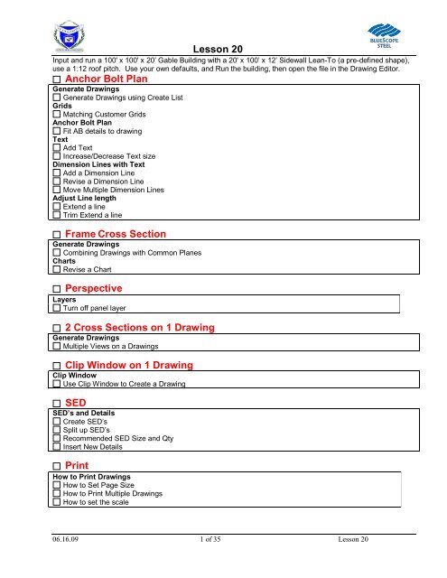
<strong>Lesson</strong> <strong>20</strong><br />
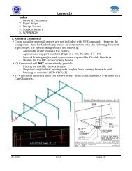
Input and run a 100' x 100' x <strong>20</strong>’ Gable Building with a <strong>20</strong>' x 100’ x 12’ Sidewall Lean-To (a pre-defined shape),<br />
use a 1:12 roof pitch. Use your own defaults, and Run the building, then open the file in the Drawing Editor.<br />
<strong>Anchor</strong> <strong>Bolt</strong> <strong>Plan</strong><br />
Generate Drawings<br />
Generate Drawings using Create List<br />
Grids<br />
Matching Customer Grids<br />
<strong>Anchor</strong> <strong>Bolt</strong> <strong>Plan</strong><br />
Fit AB details to drawing<br />
Text<br />
Add Text<br />
Increase/Decrease Text size<br />
Dimension Lines with Text<br />
Add a Dimension Line<br />
Revise a Dimension Line<br />
Move Multiple Dimension Lines<br />
Adjust Line length<br />
Extend a line<br />
Trim Extend a line<br />
<strong>Frame</strong> <strong>Cross</strong> <strong>Section</strong><br />
Generate Drawings<br />
Combining Drawings with Common <strong>Plan</strong>es<br />
Charts<br />
Revise a Chart<br />
Perspective<br />
Layers<br />
Turn off panel layer<br />
2 <strong>Cross</strong> <strong>Section</strong>s on 1 Drawing<br />
Generate Drawings<br />
Multiple Views on a Drawings<br />
Clip Window on 1 Drawing<br />
Clip Window<br />
Use Clip Window to Create a Drawing<br />
SED<br />
SED’s and Details<br />
Create SED’s<br />
Split up SED’s<br />
Recommended SED Size and Qty<br />
Insert New Details<br />
Print<br />
How to Print Drawings<br />
How to Set Page Size<br />
How to Print Multiple Drawings<br />
How to set the scale<br />
06.16.09 1 of 35 <strong>Lesson</strong> <strong>20</strong>
<strong>Lesson</strong> <strong>20</strong><br />
Matching Customer Grids<br />
This How-to provides information for customizing <strong>VP</strong> Command Drawing Grids to match architectural drawings.<br />
Note that all <strong>VP</strong>C generated reports and drawings will reflect Grid changes described in this document. All grid<br />
changes must be made prior to generating Design Reports.<br />
1.<br />
2. Select Draw/Grid Line<br />
Names from the menu<br />
shown at left.<br />
3. The Grid Line Names<br />
dialog box will appear.<br />
4. Following Grid Types<br />
may be viewed from<br />
here:<br />
Show All<br />
Building Lines<br />
<strong>Frame</strong> Lines<br />
Column Lines<br />
5. Select Display Grids<br />
to view current grid<br />
settings.<br />
06.16.09 2 of 35 <strong>Lesson</strong> <strong>20</strong>
<strong>Lesson</strong> <strong>20</strong><br />
6. To switch the Alpha and<br />
Numeric presentation of<br />
grids, select the Switch<br />
grid names option.<br />
7. Then click on the Reset<br />
Grid Names button to<br />
achieve results shown at<br />
left.<br />
8. Turn off the Switch grid<br />
names option then click<br />
the Reset Grid Names<br />
button to return to<br />
default grid layout.<br />
9. To switch the direction<br />
of the grid names, select<br />
the Label Right to Left<br />
and Label Bottom to<br />
Top buttons.<br />
10.<br />
11. Then click on the Reset<br />
Grid Names button to<br />
see the resulting switch<br />
of grids.<br />
12. Turn off the selected<br />
options then click the<br />
Reset Grid Names<br />
button to return to <strong>VP</strong>C<br />
defaults.<br />
06.16.09 3 of 35 <strong>Lesson</strong> <strong>20</strong>
<strong>Lesson</strong> <strong>20</strong><br />
13. Grid Name, Offset, X/Y<br />
Location, Angle, Type,<br />
and Orientation may be<br />
modified to match<br />
requirements. Modify<br />
Grid Name by simply<br />
typing over the existing<br />
name in the cell.<br />
14. Changes may be<br />
viewed at any time by<br />
using the Display<br />
Grids button.<br />
15.<br />
16. Click the OK button to<br />
close this dialog box.<br />
General Description of Grid Table:<br />
Name: Alpha/Numeric set of characters. This Table represents a main building with sidewall Lean-to. Each<br />
endwall/endframe is reflected twice in Table. Likewise, Column Line Grids are displayed multiple times<br />
for aligned Interior Columns or Endposts.<br />
Offset: Dimension that all Grid Lines are located from Building Envelope.<br />
X: X-coordinate of grid line using Global Coordinate system of building. This field has significance for<br />
Vertical<br />
lines only (reference only for Horizontal lines).<br />
Y: Y-coordinate of grid line using Global Coordinate system of building. This field has significance for<br />
Horizontal<br />
lines only (reference only for Vertical lines).<br />
Angle: Vertical Lines = 90, Horizontal = 180. Grids for skewed wall reflect the correct angle in Table but are<br />
drawn at<br />
either 90 or 180 degrees.<br />
Type: Three types of Grids are Building Lines, <strong>Frame</strong> Lines and Column Lines.<br />
Orientation: For reference only. This field is either Vertical or Horizontal.<br />
17. Drawings already<br />
created must be<br />
regenerated to reflect<br />
your grid changes.<br />
18. To regenerate all click<br />
on the first one, then<br />
push and hold the shift<br />
button, and then click<br />
on the last drawing.<br />
19. Then click on the<br />
Regenerate button.<br />
06.16.09 4 of 35 <strong>Lesson</strong> <strong>20</strong>
<strong>Lesson</strong> <strong>20</strong><br />
<strong>20</strong>. Choose Yes at the “Do<br />
you want to regenerate<br />
this drawing” prompt.<br />
WARNING(S):<br />
<br />
<br />
Changes to individual drawings will be lost once a drawing is regenerated. However, Grid changes are<br />
not lost by drawing regeneration.<br />
When the <strong>VP</strong>Command file is opened in the Drawing Editor, the following message may appear:<br />
This message indicates that there was a change to either Building Geometry or <strong>Frame</strong>/Column locations<br />
since the Grid Line Names were last generated in the Drawing Editor. The end result was Grids becoming<br />
out of sync with the actual Building parameters. Selecting YES to this message will cause all custom<br />
changes described in above steps to be lost.<br />
06.16.09 5 of 35 <strong>Lesson</strong> <strong>20</strong>
<strong>Lesson</strong> <strong>20</strong><br />
<strong>VP</strong>C Plot - How To Generate Drawings using Create List<br />
(Rev: 10/16/06)<br />
1. Open your <strong>VP</strong>-<br />
Command file.<br />
2. When the job opens<br />
up, the Drawing List<br />
dialog box will appear<br />
on the screen.<br />
3. Select the Drawing<br />
Size prior to generating<br />
any drawings.<br />
4. Select the Create List<br />
button to generate a<br />
list of drawings<br />
pertaining to that<br />
project.<br />
5. <strong>VP</strong>C will default to<br />
select all drawings.<br />
This will generate all<br />
the drawings on this<br />
project.<br />
6. If you want all the<br />
drawings generated<br />
click OK<br />
7. You can select the<br />
Specify Drawings<br />
button to change what<br />
will be generated.<br />
Select or De-Select the<br />
appropriate items in<br />
the list.<br />
8. Once you have<br />
selected the drawings<br />
you want generated hit<br />
OK.<br />
06.16.09 6 of 35 <strong>Lesson</strong> <strong>20</strong>
<strong>Lesson</strong> <strong>20</strong><br />
<strong>VP</strong>C Plot - How To have the AB Details fit the drawing<br />
1. Select the <strong>Anchor</strong> <strong>Bolt</strong> <strong>Plan</strong><br />
that has your details.<br />
2. Click on the print preview<br />
button to view the Details, here<br />
you can see there is plenty of<br />
space on the drawing for the<br />
AB details.<br />
3. click on the Close button to go<br />
back to the Drawing Data<br />
screen.<br />
4. From this window choose the<br />
revise button or use the Edit,<br />
Revise from the dropdown<br />
menu.<br />
06.16.09 7 of 35 <strong>Lesson</strong> <strong>20</strong>
<strong>Lesson</strong> <strong>20</strong><br />
5. Click on the Detail sets on the<br />
right, then click on the Detail<br />
Set1 in the grid.<br />
6. Then click on the Revise<br />
button.<br />
7. Choose Fit on Drawing radio<br />
button, and click OK.<br />
8. Then click OK through the next<br />
screen also.<br />
9. Print Preview to make sure<br />
your changes were correct.<br />
You should see that the details<br />
fill the page.<br />
06.16.09 8 of 35 <strong>Lesson</strong> <strong>20</strong>
<strong>Lesson</strong> <strong>20</strong><br />
<strong>VP</strong>C Plot - How To Add Text<br />
(Rev: 10/16/06)<br />
1. Select a drawing from<br />
the Drawing List dialog<br />
box.<br />
2. Move or close the<br />
drawing list dialog box<br />
out of your way.<br />
3. Left mouse click on the<br />
Insert Text Tab.<br />
4. Insert the Text line by left<br />
mouse click at the start<br />
point at the desired<br />
location and then left<br />
mouse click a second<br />
time at the end of the<br />
desired location.<br />
06.16.09 9 of 35 <strong>Lesson</strong> <strong>20</strong>
<strong>Lesson</strong> <strong>20</strong><br />
5. The Text Box will<br />
appear. Here you can<br />
type any notes you need<br />
to add to the drawings.<br />
<strong>VP</strong>C Plot - How To Increase or decrease Text size<br />
Note: If you need to use<br />
Multiple Lines you will need<br />
to hold down the Ctrl Key<br />
and hit Enter.<br />
6. At this point you can use<br />
the steps in the how-to’s<br />
“Move a Single Text”<br />
or “Move Multiple Text”<br />
to move your added text<br />
if the placement was off.<br />
7. Print Preview before<br />
printing to ensure the<br />
text is correct.<br />
8. If the preview looks<br />
correct, pick a different<br />
drawing. The system will<br />
then ask if you want to<br />
save, click yes<br />
1. Select a<br />
drawing from<br />
the Drawing<br />
List dialog<br />
box.<br />
2. Move or close<br />
the drawing<br />
list dialog box<br />
out of your<br />
way.<br />
3. Left mouse<br />
click on the<br />
Increase Text<br />
button.<br />
06.16.09 10 of 35 <strong>Lesson</strong> <strong>20</strong>
<strong>Lesson</strong> <strong>20</strong><br />
4. By clicking on<br />
the button a<br />
few times your<br />
text will<br />
increase.<br />
<strong>VP</strong>C Plot - How To Add a Dimension Line<br />
1. Select a drawing from the<br />
Drawing List dialog box.<br />
2. Move or close the drawing<br />
list dialog box out of<br />
your way.<br />
3. Left mouse click on the<br />
Insert Dimensions Tab.<br />
06.16.09 11 of 35 <strong>Lesson</strong> <strong>20</strong>
<strong>Lesson</strong> <strong>20</strong><br />
4. Insert the Dimension line<br />
by left mouse click at<br />
the start point at the<br />
desired location and<br />
then left mouse click a<br />
second time at the end<br />
of the desired location.<br />
5. Right Mouse click when<br />
you are finished<br />
creating the Dimension<br />
line<br />
6. At this point you can use<br />
the steps in the how-to’s<br />
7. To move your added<br />
Dimension line if the<br />
placement was off<br />
8. Print Preview before<br />
printing to ensure the<br />
dimension is correct.<br />
9. If the preview looks<br />
correct, pick a different<br />
drawing. The system will<br />
then ask if you want to<br />
save, click yes<br />
<strong>VP</strong>C Plot - How To Revise a Dimension Line<br />
(New: 10/16/06)<br />
1. Select a drawing from<br />
the Drawing List dialog<br />
box.<br />
2. Move or close the<br />
drawing list dialog box<br />
out of your way.<br />
3. Double Left mouse click<br />
on the dimension line<br />
you want to revise.<br />
4. In this screen there are<br />
numerous items that<br />
can be modified.<br />
X,Y Coordinates<br />
06.16.09 12 of 35 <strong>Lesson</strong> <strong>20</strong>
<strong>Lesson</strong> <strong>20</strong><br />
Text<br />
5. X,Y – This option allows the user to<br />
revise the location of text or dimensions<br />
by changing the end reference points.<br />
The X-direction is horizontal and the Y-<br />
direction is vertical.<br />
6. When the X,Y coordinates have been<br />
revised the text can be updated to the<br />
new Dimension Length by selecting the<br />
button<br />
7. Text - This option will<br />
display the selected text<br />
or dimension and can<br />
be overridden.<br />
Text Alignment<br />
8. Above - This Text<br />
Alignment option will<br />
locate the selected text or<br />
dimension to the left of<br />
vertical dimension lines or<br />
above horizontal<br />
dimension lines.<br />
9. Center - This Text<br />
Alignment option will<br />
center the selected text<br />
or dimension within its<br />
dimension line.<br />
Font<br />
10. Below - This Text<br />
Alignment option will<br />
locate the selected text<br />
or dimension to the right<br />
of the vertical<br />
dimension lines or<br />
below horizontal<br />
dimension lines.<br />
11. Font - This option will<br />
allow the size of the font<br />
on the selected text or<br />
dimensions to be<br />
revised.<br />
Offset<br />
06.16.09 13 of 35 <strong>Lesson</strong> <strong>20</strong>
<strong>Lesson</strong> <strong>20</strong><br />
12. Offset - This field<br />
locates the selected text<br />
or dimension the value<br />
input from its text<br />
insertion point. This<br />
value is in inches. A<br />
positive dimension will<br />
locate the text or<br />
dimension to the right or<br />
above the selected<br />
point, a negative<br />
dimension will locate<br />
the text or dimension to<br />
the left or below the<br />
selected point.<br />
06.16.09 14 of 35 <strong>Lesson</strong> <strong>20</strong>
<strong>Lesson</strong> <strong>20</strong><br />
Text Location<br />
13. Text Location - This<br />
option will locate the<br />
selected text or<br />
dimension using the<br />
input percentage<br />
number within the<br />
selected space. For<br />
example, if 50% is<br />
input, the selected text<br />
or dimension will be<br />
located 50% (or onehalf)<br />
of the way from<br />
end one of the text<br />
insertion point.<br />
Text Position<br />
14. Middle - This Text<br />
Position option will be<br />
used in conjunction with<br />
the percentage value<br />
input in the Text<br />
Location field to locate<br />
the middle of the text or<br />
dimension in its<br />
dimension line.<br />
15. Left - This Text Position<br />
option will be used in<br />
conjunction with the<br />
percentage value input<br />
in the Text Location<br />
field to locate the left<br />
edge of the text or<br />
dimension in its<br />
dimension line.<br />
16. Right - This Text<br />
Position option will be<br />
used in conjunction with<br />
the percentage value<br />
input in the Text<br />
Location field to locate<br />
the right edge of the<br />
text or dimension in its<br />
dimension line.<br />
06.16.09 15 of 35 <strong>Lesson</strong> <strong>20</strong>
<strong>Lesson</strong> <strong>20</strong><br />
Dimension Style<br />
17. Standard - This<br />
Dimension Style option<br />
will apply the default<br />
dimensioning for the<br />
dimension type. For<br />
example; dimensions will<br />
default to the dimension<br />
numbers and dimension<br />
lines, text will default to<br />
the words and/or<br />
numbers only with no<br />
dimension lines. The<br />
user may override these<br />
defaults.<br />
18. Text and Line - This<br />
Dimension Style will<br />
display text or<br />
dimensions and a<br />
dimension line without<br />
extension lines.<br />
19. Text - This Dimension<br />
Style will display the text<br />
or dimension only with<br />
no dimension lines<br />
and/or extension lines.<br />
<strong>20</strong>. Run - This Dimension<br />
Style will show the<br />
selected text or<br />
dimension in a ‘‘running’’<br />
dimensioning format.<br />
This will be displayed as<br />
the text or dimension<br />
with its dimension line<br />
extending to its end<br />
extension line, the<br />
starting extension line<br />
will not be displayed.<br />
Symbol<br />
21. Symbol - None option<br />
will display the text<br />
and/or dimension only.<br />
06.16.09 16 of 35 <strong>Lesson</strong> <strong>20</strong>
<strong>Lesson</strong> <strong>20</strong><br />
22. Symbol - Circle option<br />
will place a circle<br />
around the selected text<br />
or dimension.<br />
23. Symbol - Rectangle<br />
option will place a<br />
rectangle around the<br />
selected text or<br />
dimension.<br />
24. Symbol – Hexagon<br />
option will place a<br />
hexagon around the<br />
selected text or<br />
dimension.<br />
25. Symbol - Grid Bubble<br />
option will place a grid<br />
bubble around the<br />
selected text or<br />
dimension. This would<br />
be use in conjunction<br />
with Dimension Style of<br />
Text<br />
06.16.09 17 of 35 <strong>Lesson</strong> <strong>20</strong>
<strong>Lesson</strong> <strong>20</strong><br />
Arrowheads<br />
26. Arrowheads – This<br />
option allows the use of<br />
optional Arrowhead<br />
styles to be used on<br />
text and dimensions.<br />
Shown is the various<br />
styles using both with<br />
the “Std.” And “Text &<br />
Line” dimension styles.<br />
27. Once desired changes have been made OK out.<br />
28. If the dimension is not what you want repeat step 3.<br />
29. Print Preview before printing to ensure the dimension<br />
is correct.<br />
30. If the preview looks correct, pick a different drawing.<br />
The system will then ask if you want to save, click<br />
yes.<br />
<strong>VP</strong>C Plot - How To Move Multiple Dimension Lines<br />
(Rev: 10/16/06)<br />
There are two methods of moving Dimension Lines.<br />
Method 1 Method 1<br />
1. Select a drawing from the<br />
Drawing List dialog box.<br />
2. Move or close the drawing<br />
list dialog box out of your<br />
way.<br />
3. Left mouse click on all the<br />
dimension lines you want<br />
to move at once. They will<br />
highlight as you click them.<br />
4. Hold the left mouse button<br />
down on the dimension<br />
you want the move based<br />
off of, and release the<br />
button where you want the<br />
dimension to be.<br />
5. If the dimension is not<br />
where you want it repeat<br />
step 2.<br />
6. Once you are done moving<br />
the selected item, you<br />
MUST right click to unselect<br />
the items.<br />
7. Print Preview before<br />
printing to ensure the<br />
dimensions are correct.<br />
06.16.09 18 of 35 <strong>Lesson</strong> <strong>20</strong>
<strong>Lesson</strong> <strong>20</strong><br />
8. If the preview looks correct,<br />
pick a different drawing.<br />
The system will then ask if<br />
you want to save, click<br />
yes.<br />
Note: When selecting multiple<br />
dimensions, make sure you<br />
click the desired dimension<br />
and release the button<br />
BEFORE moving to the next<br />
dimension. If the button is still<br />
depressed when you move to<br />
the next dimension you will<br />
move all earlier dimensions<br />
based on this move.<br />
06.16.09 19 of 35 <strong>Lesson</strong> <strong>20</strong>
<strong>Lesson</strong> <strong>20</strong><br />
Method 2<br />
Coordinate Space - This option is to establish how the line is located.<br />
Model - This will locate the dimension line based off the work point,<br />
usually lower left corner of the plane you are working on.<br />
Paper - This will locate the dimension line based off the Paper size,<br />
upper left corner of the page<br />
Method 2<br />
31. Select a drawing<br />
from the Drawing List<br />
dialog box.<br />
32. Move the drawing list<br />
dialog box out of your<br />
way.<br />
33. Left mouse click on<br />
all the dimension lines<br />
with the same Offset that<br />
you want to move at<br />
once. They will turn<br />
white as you click them.<br />
34. Double Left mouse<br />
click on the last<br />
dimension line you want<br />
to move.<br />
35. Highlight the Offset<br />
and revise to increase or<br />
decrease the offset from<br />
a location.<br />
36. OK out.<br />
37. If the dimension is<br />
not where you want it<br />
repeat step 2.<br />
38. Print Preview before<br />
printing to ensure the<br />
dimension is correct.<br />
39. If the preview looks<br />
correct, pick a different<br />
drawing. The system will<br />
then ask if you want to<br />
save, click yes.<br />
Note: When selecting<br />
multiple dimensions, make<br />
sure you click the desired<br />
dimension and release the<br />
button BEFORE moving to<br />
the next dimension. If the<br />
button is still depressed<br />
when you move to the next<br />
dimension you will move all<br />
earlier dimensions based on<br />
this move.<br />
<strong>VP</strong>C Plot - How To use the Trim & Extend Line Features<br />
(New: 10/16/06)<br />
9. There are 2 functions to Extend or Trim a Line.<br />
06.16.09 <strong>20</strong> of 35 <strong>Lesson</strong> <strong>20</strong>
<strong>Lesson</strong> <strong>20</strong><br />
(Trim Line)<br />
(Extend Line)<br />
10. Each of these functions can be accessed in one of two ways<br />
a. Select the Tool from the Tool Bar<br />
b. Go to Edit in the Menu Bar and select the Tool<br />
11. First select the Line that you want to Trim back to or Extend<br />
to. This is the Intersection Line.<br />
12. Next select the Line that you want to Trim back or Extend.<br />
This Line should be selected on the Side of the Intersection<br />
Line that you want to keep.<br />
13. Then select the Trim Line or Extend Line as required.<br />
14. Now the Selected Line will be Extended or Trimmed back to<br />
the Intersection Line.<br />
Combining Drawings with Common <strong>Plan</strong>es<br />
06.16.09 21 of 35 <strong>Lesson</strong> <strong>20</strong>
<strong>Lesson</strong> <strong>20</strong><br />
Rev: OK 5/06/02<br />
This How-to describes the <strong>VP</strong> Command feature of combining drawings that share a common plane. The<br />
following steps refer to generating a drawing for a Rigid <strong>Frame</strong> combined with Lean-to.<br />
Other instances where this <strong>VP</strong> Command feature could be used are for <strong>Frame</strong>s Across Shapes, multiple Portal<br />
<strong>Frame</strong>s on a Sidewall, Wall Secondary, Covering, and Liner sharing the same plane.<br />
9. Go to <strong>VP</strong>C Plot and open<br />
your <strong>VP</strong> Command file.<br />
10. The Drawing List dialog box<br />
will appear on the screen as<br />
shown.<br />
11. Select the Drawing Size prior<br />
to generating any drawings.<br />
12. Select the Drawing Styles as<br />
Erection Drawing.<br />
13. Move Drawing List window<br />
as far left and down but still<br />
have the Insert Button in<br />
view. Select the Insert<br />
Button.<br />
14. Select the Type of Erection<br />
Drawing you want to<br />
generate.<br />
15. Select from the Available<br />
Locations the first plane of<br />
the drawing you want to<br />
generate.<br />
16. Hold down the Ctrl key and<br />
select the next plane(s) of<br />
the drawing you want to<br />
generate.<br />
17. Once you have selected the<br />
locations you want<br />
generated, select OK.<br />
06.16.09 22 of 35 <strong>Lesson</strong> <strong>20</strong>
<strong>Lesson</strong> <strong>20</strong><br />
Note: When you select an Available Location the Drawing in the background will highlight the selected plane.<br />
See graphics below for resulting drawings from various selections:<br />
06.16.09 23 of 35 <strong>Lesson</strong> <strong>20</strong>
<strong>Lesson</strong> <strong>20</strong><br />
18. Information within a Surface may be<br />
combined with use of Layers. Select<br />
the Layer Icon and Click On/Off the<br />
required layers. See sample of Roof<br />
Secondary combined with Rods.<br />
WARNING(S):<br />
Combining drawings on common surfaces (planes) can be done providing the Available Locations list shown<br />
in Steps 6 through 9 includes the surfaces in question.<br />
When plotting <strong>Frame</strong> <strong>Cross</strong>-sections with <strong>Frame</strong>s Across Shapes, the system generates frames per shapes.<br />
(Segmented). Full-length cross-sections can be accomplished by selecting that frame within all shapes that<br />
frame passes through.<br />
06.16.09 24 of 35 <strong>Lesson</strong> <strong>20</strong>
<strong>Lesson</strong> <strong>20</strong><br />
<strong>VP</strong>C Plot - How To Revise a Chart<br />
(Rev: 01/31/03)<br />
1. Select a drawing from<br />
the Drawing List dialog<br />
box.<br />
2. Move or close the<br />
drawing list dialog box<br />
out of your way.<br />
3. Double Left mouse click<br />
at the upper left of the<br />
chart or,<br />
4. Click on the Revise<br />
button on the toolbar.<br />
5. Select Charts from<br />
the Current Drawing<br />
Data screen.<br />
6. Highlight the Chart you<br />
want to revise and click<br />
on the Revise button.<br />
06.16.09 25 of 35 <strong>Lesson</strong> <strong>20</strong><br />
7. In this screen you revise<br />
any of these fields<br />
Title<br />
Add Chart Info<br />
Chart Direction<br />
Column Width<br />
X,Y Location<br />
Font Size<br />
8. Note: the X,Y<br />
coordinates are from<br />
the Upper Left corner of<br />
the drawing page<br />
9. OK Out<br />
10. Print Preview before<br />
printing to ensure the<br />
dimension is correct.<br />
11. If the preview looks<br />
correct, pick a different
<strong>Lesson</strong> <strong>20</strong><br />
drawing. The system<br />
will then ask if you want<br />
to save, click yes<br />
06.16.09 26 of 35 <strong>Lesson</strong> <strong>20</strong>
<strong>Lesson</strong> <strong>20</strong><br />
<strong>VP</strong>C Plot - How To use Layers<br />
(Rev: 01/31/03)<br />
Layers are sections of a drawing. A specific layer corresponds with a specific group of lines on the drawing.<br />
These layers are different colors, in order to keep them identifiable, and can be modified to be similar to another<br />
layer. This concept is similar to other major drawing programs, which allows ease of import into other programs.<br />
1. Select a drawing from<br />
the Drawing List dialog<br />
box.<br />
2. Move or close the<br />
drawing list dialog box<br />
out of your way.<br />
3. Left mouse click on the<br />
Layers Tab.<br />
4.<br />
5. Under the Drawing<br />
Layer screen, there is<br />
a grid, which is made<br />
up of.<br />
6. Layer Name<br />
7. Show Box<br />
8. Style<br />
9. Width<br />
10. Color<br />
11. The Layer Name corresponds to the layer associated with the drawing.<br />
12. The Show Box is a check box, if the check mark is shown then the layer will be exposed on the drawing.<br />
If the check mark is not shown then the layer will not be exposed on the drawing.<br />
13. The Style column is to correspond with the type of style associated with the lines on the drawings. The<br />
styles are; ( Solid, Dash, Dot, Dash Dot, Dash Dot Dot ).<br />
14. Note: The Width of the Lines must = 0 on any Line style other than “Solid” in order to print that style.<br />
15. The color of a layer is created by the system, but the user can revise the colors<br />
<strong>VP</strong>C Plot – How to Create a Custom Drawing<br />
With Multiple Views on a Drawing<br />
To create a Custom Drawing combining two drawings on the same page you must<br />
first have the drawings generated and in the Drawing List.<br />
06.16.09 27 of 35 <strong>Lesson</strong> <strong>20</strong>
<strong>Lesson</strong> <strong>20</strong><br />
1. Open your <strong>VP</strong>-Command<br />
file.<br />
2. When the job opens up,<br />
the Drawing List dialog<br />
box will appear on the<br />
screen.<br />
3. Select the Paper Size prior<br />
to generating any<br />
drawings.<br />
A 8.5” x 11”<br />
B 11” x 17”<br />
C 17” x 22”<br />
D 22” x 34”<br />
4. Select the Drawing Styles<br />
as Custom Drawing<br />
5. Select the Insert Button.<br />
6. Select the 1st Drawing<br />
from the list.<br />
7. Click the 2nd Drawing<br />
Check Box.<br />
8. Select either the<br />
Horizontal Split<br />
(Drawings will be located<br />
at the top and bottom of<br />
page)<br />
Vertical Split<br />
(Drawings will be located<br />
at the left and right of<br />
page.)<br />
9. Select the 2nd Drawing<br />
from the list.<br />
10. Once you have selected<br />
the drawings you want<br />
generated hit OK.<br />
11. This New Drawing will be<br />
located at the Top of the<br />
Drawing List.<br />
12. Select this Drawing and<br />
click Revise.<br />
13. Add the desired Title to<br />
the Drawing.<br />
Note: Any modifications to this Drawing MUST be done to the Original Drawing that has been selected from the<br />
List.<br />
<strong>VP</strong>C Plot - How To Use Clip Window to Create a Drawing<br />
(New: 11/2/06)<br />
06.16.09 28 of 35 <strong>Lesson</strong> <strong>20</strong>
<strong>Lesson</strong> <strong>20</strong><br />
1. Open your <strong>VP</strong>-Command file.<br />
2. When the job opens up, the<br />
Drawing List dialog box will<br />
appear on the screen.<br />
3. Select the Drawing you wish<br />
to use Clip Window to create<br />
a New Drawing from.<br />
4. Click on the Clip Window<br />
button on Drawing List dialog<br />
box.<br />
5. Clip the desired portion of the<br />
drawing by left mouse click at<br />
the start point at the desired<br />
location and then left mouse<br />
click a second time at the end<br />
of the desired location.<br />
6. This will add a New Drawing<br />
located at the Bottom of the<br />
Drawing List.<br />
7. Select this Drawing and<br />
modify it to the desired<br />
information you want on<br />
your Drawing.<br />
8. This Drawing will modify<br />
like any other drawing.<br />
Hide Anything<br />
Copy Anything<br />
Move Anything<br />
Add Anything<br />
Revise Anything<br />
Modify Margins<br />
<strong>VP</strong>C Plot - How To Create SED’s<br />
(Rev: 08/01/03)<br />
06.16.09 29 of 35 <strong>Lesson</strong> <strong>20</strong>
<strong>Lesson</strong> <strong>20</strong><br />
9. Open your <strong>VP</strong>-Command file.<br />
10. When the job opens up, the Drawing List dialog box will appear on the<br />
screen.<br />
11. Select the Paper Size prior to generating any drawings.<br />
A 8.5” x 11”<br />
B 11” x 17”<br />
C 17” x 22”<br />
D 22” x 34”<br />
12. Inside the Drawing List dialog box, look at the Standard Erection Details<br />
radio button on the right side.<br />
13. Select the Radio Button for the type of details you want on the drawing<br />
you are about to create. The available types are;<br />
All Building Details<br />
Wall Secondary<br />
Roof Secondary<br />
Covering and Trim<br />
Custom SED Sheet<br />
14. Click on the Insert button.<br />
15. A drawing will now appear in the Drawing List dialog box.<br />
16. Select this drawing.<br />
17. Move or close the drawing list dialog box out of your way.<br />
18. Displayed is the entire set of generated details.<br />
<strong>VP</strong>C Plot - How To Split up SED’s<br />
(Rev: 01/31/03)<br />
19. Open your <strong>VP</strong>-Command file.<br />
<strong>20</strong>. When the job opens up, the Drawing List dialog box will appear on the<br />
screen.<br />
21. Select the SED drawing from the Drawing List dialog box you wish to split<br />
up.<br />
22. Highlight the box next to the Split Up button. Fill in the number you wish<br />
to see on each page.<br />
23. Click on the Split Up button. This will create several drawings with the<br />
number of details you picked.<br />
24. Inside the Drawing List dialog box, the original set of details is still there.<br />
At the bottom of the Drawing List are the new SED’s you created when the<br />
Split Up button was pushed.<br />
25. Pick on the new SED drawings.<br />
26. Move or close the drawing list dialog box out of your way.<br />
27. The details will display on the screen.<br />
See How To “Recommended SED Sizes and Qty's” to see a list of the recommended SED size and qty per<br />
page.<br />
<strong>VP</strong>C Plot - Recommended SED Size and<br />
Quantity based on Drawing Size<br />
(Revised: 03/16/04)<br />
See How To “Set Size of SED's” to set detail size.<br />
Paper Size<br />
‘B’<br />
11” x<br />
17”<br />
‘B’<br />
11” x<br />
17”<br />
‘C’<br />
17” x<br />
22”<br />
‘C’<br />
17” x 22”<br />
‘D’<br />
22” x 34”<br />
06.16.09 30 of 35 <strong>Lesson</strong> <strong>20</strong><br />
‘D’<br />
22” x 34”
<strong>Lesson</strong> <strong>20</strong><br />
Number of Details per Page 8 15 12 15 15 18<br />
Number of Details (last one<br />
blank) for Engineer Stamp<br />
7 14 11 14 14 17<br />
Detail Width 0/4/1 0/3/4 0/5/5 0/4/4 0/6/9 0/5/7<br />
Detail Height 0/4/9 0/3/1 0/4/12 0/4/12 0/6/2 0/6/2<br />
Number of Details in Row 4 5 4 5 5 6<br />
Number of Details in Column 2 3 3 3 3 3<br />
Note: if your SED’s do not print dark enough on the C & D size<br />
drawings, try to keep the SED size at 0/6/0 and above.<br />
(This dimension may vary per Plotter)<br />
<strong>VP</strong>C Plot - How To Insert New Details<br />
(Rev: 11/2/06)<br />
1. Open your <strong>VP</strong>-Command file.<br />
2. When the job opens up, the<br />
Drawing List dialog box will appear<br />
on the screen.<br />
3. Select the SED’s page in the<br />
Drawing List dialog.<br />
4. Select the Revise Button.<br />
5. Click on the Insert button inside the<br />
dialog box.<br />
6.<br />
06.16.09 31 of 35 <strong>Lesson</strong> <strong>20</strong>
<strong>Lesson</strong> <strong>20</strong><br />
7. Select the desired detail from the<br />
list or multi-select details by holding<br />
the CTRL key down and select<br />
other details to add.<br />
Note: Use ‘’Files of Type’’ to filter details.<br />
8. OK out.<br />
9. You can also delete any detail, by<br />
picking the detail in the list and<br />
clicking on the Delete button.<br />
Print Preview before printing to ensure the<br />
Details are correct.<br />
<strong>VP</strong>C Plot – How to Set Page Size<br />
(Rev: 11/02/06)<br />
Following is the Steps to set the Page Size for your drawings.<br />
Print Setup<br />
1. Go to File - Print<br />
Setup from the<br />
menu.<br />
2. Select the desired<br />
printer or plotter<br />
from the Printer<br />
Name field.<br />
3. Select the Paper<br />
Size you wish to<br />
use. (B size paper<br />
uses 11 x 17 paper)<br />
4. Select Portrait or<br />
Landscape in the<br />
Orientation box.<br />
Note: Some printers<br />
require you to go into the<br />
Properties button to<br />
change the paper size and<br />
06.16.09 32 of 35 <strong>Lesson</strong> <strong>20</strong>
<strong>Lesson</strong> <strong>20</strong><br />
orientation.<br />
5. Click the OK button.<br />
Note: You must have the printer drivers loaded on your machine to access<br />
different paper sizes. See your System Administrator for the appropriate<br />
drivers.<br />
Generate Drawings<br />
1. Generate Drawings per the instruction<br />
on how to<br />
“Generate Drawings using Create List”<br />
or “Generate a Specific Drawing”.<br />
2. Select the Drawing Size prior to<br />
generating any drawings.<br />
Set Border<br />
3. Generate Drawings per the<br />
instruction on how to<br />
“Set Border on Drawings”.<br />
4. Left mouse click on the Title Block<br />
and Cover Tab<br />
or select from the Drop Down menu, pick<br />
Draw/Default Title Block.<br />
To change the border type/size you can click<br />
the Browse button on either the Cover Sheet<br />
or All Other Drawings to whatever type/size<br />
you desire.<br />
To see the drawing click the Print Preview button on the toolbar or go to File-Print Preview from the menu.<br />
06.16.09 33 of 35 <strong>Lesson</strong> <strong>20</strong><br />
5. Once you are satisfied<br />
with the drawings, go<br />
back to the Drawing<br />
List dialog box.<br />
6. Select as many<br />
drawings as you wish<br />
to print at one time by<br />
holding the Ctrl key<br />
down, on the<br />
keyboard, and left<br />
mouse click each of<br />
the drawings you<br />
want. If you want to<br />
print all drawings, then<br />
hold down the Shift<br />
key, on the keyboard,
<strong>Lesson</strong> <strong>20</strong><br />
and pick the first<br />
drawing in the list,<br />
then the last drawing.<br />
All drawings should<br />
then be selected.<br />
7. Next click on the Print<br />
button inside the<br />
dialog box.<br />
8. Click the OK button on<br />
the Print dialog box<br />
when it comes up<br />
06.16.09 34 of 35 <strong>Lesson</strong> <strong>20</strong>
<strong>Lesson</strong> <strong>20</strong><br />
<strong>VP</strong>C Plot - How To Print Multiple Drawings<br />
(New: 11/02/06)<br />
1. Select a drawing from the Drawing List dialog<br />
box.<br />
2. Move or close the drawing list dialog box out of<br />
your way.<br />
3. Left mouse click on the Print Preview Tab.<br />
4. Look for over-plotting, Close and fix if required.<br />
5. Continue doing steps 1 thru 4 until all drawings<br />
are checked and fixed.<br />
6. Once you are satisfied with the<br />
drawings, go back to the<br />
Drawing List dialog box.<br />
7. Select as many drawings as<br />
you wish to print at one time<br />
by holding the Ctrl key down,<br />
on the keyboard, and left<br />
mouse click each of the<br />
drawings you want. If you want<br />
to print all drawings, then hold<br />
down the Shift key, on the<br />
keyboard, and pick the first<br />
drawing in the list, then the last<br />
drawing. All drawings should<br />
then be selected.<br />
8. Next click on the Print button<br />
inside the dialog box.<br />
9. Click the OK button on the<br />
Print dialog box when it comes<br />
up<br />
06.16.09 35 of 35 <strong>Lesson</strong> <strong>20</strong>