Lesson 20 Anchor Bolt Plan Frame Cross Section ... - VP Buildings
Lesson 20 Anchor Bolt Plan Frame Cross Section ... - VP Buildings
Lesson 20 Anchor Bolt Plan Frame Cross Section ... - VP Buildings

You also want an ePaper? Increase the reach of your titles
YUMPU automatically turns print PDFs into web optimized ePapers that Google loves.
<strong>Lesson</strong> <strong>20</strong><br />
Rev: OK 5/06/02<br />
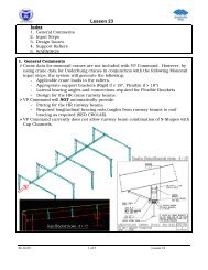
This How-to describes the <strong>VP</strong> Command feature of combining drawings that share a common plane. The<br />
following steps refer to generating a drawing for a Rigid <strong>Frame</strong> combined with Lean-to.<br />
Other instances where this <strong>VP</strong> Command feature could be used are for <strong>Frame</strong>s Across Shapes, multiple Portal<br />
<strong>Frame</strong>s on a Sidewall, Wall Secondary, Covering, and Liner sharing the same plane.<br />
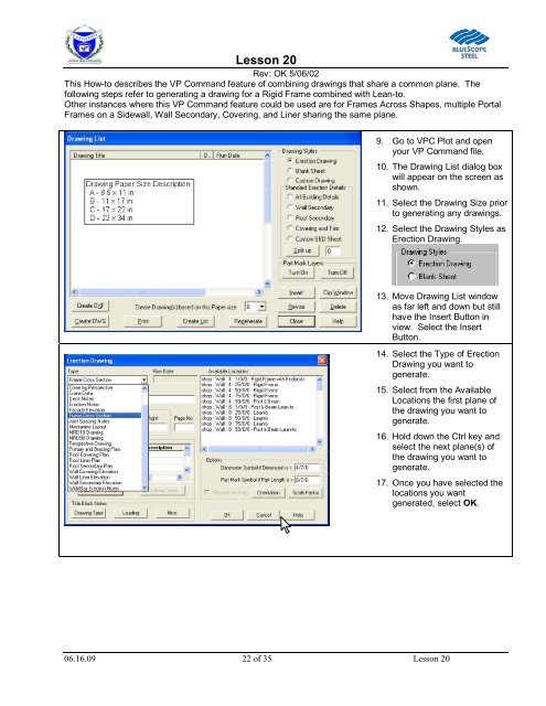
9. Go to <strong>VP</strong>C Plot and open<br />
your <strong>VP</strong> Command file.<br />
10. The Drawing List dialog box<br />
will appear on the screen as<br />
shown.<br />
11. Select the Drawing Size prior<br />
to generating any drawings.<br />
12. Select the Drawing Styles as<br />
Erection Drawing.<br />
13. Move Drawing List window<br />
as far left and down but still<br />
have the Insert Button in<br />
view. Select the Insert<br />
Button.<br />
14. Select the Type of Erection<br />
Drawing you want to<br />
generate.<br />
15. Select from the Available<br />
Locations the first plane of<br />
the drawing you want to<br />
generate.<br />
16. Hold down the Ctrl key and<br />
select the next plane(s) of<br />
the drawing you want to<br />
generate.<br />
17. Once you have selected the<br />
locations you want<br />
generated, select OK.<br />
06.16.09 22 of 35 <strong>Lesson</strong> <strong>20</strong>