
You also want an ePaper? Increase the reach of your titles
YUMPU automatically turns print PDFs into web optimized ePapers that Google loves.
Adding Design Details<br />
5. In the Extrude dialog box, click the Cut option, click<br />
the down arrow under Extents and select All, click the<br />
Centered option, and then click OK.<br />
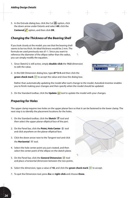
Changing the Thickness of the Bearing Shell<br />
If you look closely at the model, you see that the bearing shell<br />
seems to be too thick. An ideal thickness would be 2 mm. The<br />
formula we used previously was d1-1. Since you want to<br />
reference the diameter of the ellipse rather than the radius,<br />
you can simply modify the equation.<br />
1. Since Sketch2 is still active, simply double-click the 14.5 dimension<br />
to edit the value.<br />
2. In the Edit Dimension dialog box, type d1*2-4 and then click the<br />
green check mark to accept the value and close the dialog box.<br />
Rather than automatically updating the model after each change to the model, <strong>Autodesk</strong> Inventor enables<br />
you to finish making your changes and then specify when the model should be updated.<br />
3. On the Standard toolbar, click the Update tool to update the model with your changes.<br />
Preparing for Holes<br />
The upper clamp requires two holes on the upper planar face so that it can be fastened to the lower clamp. The<br />
next step is to identify the placement locations for the holes.<br />
1. On the Standard toolbar, click the Sketch tool and<br />
then select the upper planar elliptical face of the part.<br />
2. On the Panel bar, click the Point, Hole Center tool<br />
and click anywhere on the planar elliptical face.<br />
3. Click the down arrow next to the Tangent tool and click<br />
the Horizontal tool.<br />
4. Select the hole center point you just created, and then<br />
select the center point of the ellipse on the sketch plane.<br />
5. On the Panel bar, click the General Dimension tool<br />
and place a horizontal dimension between the two points.<br />
6. Select the dimension, type a value of 18, and click the green check mark to accept.<br />
7. To quit the Dimension tool, press Esc or right-click and choose Done.<br />
26