
Create successful ePaper yourself
Turn your PDF publications into a flip-book with our unique Google optimized e-Paper software.
Using iMate—Intelligent Mating of Components<br />
To create the hole feature:<br />
1. On the Panel bar, click the Hole tool.<br />
2. In the Holes dialog box, select Through All for the termination,<br />
change the diameter to 7 mm, and then click OK.<br />
Creating a Flat Pattern<br />
Before you add intelligence to the hole, you should see how easily you<br />
can create a flat pattern of your sheet metal part. Flat patterns are<br />
basically the “flat blanks” used to manufacture sheet metal parts.<br />
To create a flat pattern for your sheet metal part:<br />
• On the Panel bar, click the Flat Pattern tool.<br />
<strong>Autodesk</strong> Inventor automatically performs the required calculations for the<br />
bending allowance and correctly displays the flat pattern as a flat 3D part. You can<br />
also easily identify the bending lines and bending zones on the flat blank.<br />
If you want, you can create engineering drawings using both the folded and<br />
unfolded versions of the sheet metal part on the same drawing sheet. Flat<br />
patterns can also be exported as AutoCAD® DWG or DXF files and can then be<br />
imported into CAM (Computer Aided Machining) software for nesting, punching,<br />
or even laser cutting.<br />
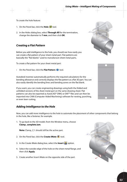
Adding Intelligence to the Hole<br />
Now, you can add more intelligence to the hole to automate the placement of other components that belong<br />
in the hole, like a fastener, for example.<br />
1. To go back to the 3D model, from the Window menu, choose<br />
Clamp_complete.iam.<br />
Note: Clamp_C:1 should still be the active part.<br />
2. On the Panel bar, click the Create iMate tool.<br />
3. In the Create iMate dialog box, select the Insert option.<br />
4. Select the outside edge of the hole on the sheet metal flange, and<br />
then click Apply.<br />
5. Create another Insert iMate on the opposite side of the part.<br />
53