
You also want an ePaper? Increase the reach of your titles
YUMPU automatically turns print PDFs into web optimized ePapers that Google loves.
Working with Multiple Parts in an Assembly<br />
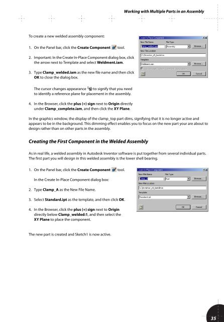
To create a new welded assembly component:<br />
1. On the Panel bar, click the Create Component tool.<br />
2. Important: In the Create In-Place Component dialog box, click<br />
the arrow next to Template and select Weldment.iam.<br />
3. Type Clamp_welded.iam as the new file name and then click<br />
OK to close the dialog box.<br />
The cursor changes appearance to signify that you need<br />
to identify a reference plane for placement in the assembly.<br />
4. In the Browser, click the plus (+) sign next to Origin directly<br />
under Clamp_complete.iam, and then click the XY Plane.<br />
In the graphics window, the display of the clamp_top part dims, signifying that it is no longer active and<br />
appears to be in the background. This dimming effect enables you to focus on the new part your are about to<br />
design rather than on other parts in the assembly.<br />
Creating the First Component in the Welded Assembly<br />
As in real life, a welded assembly in <strong>Autodesk</strong> Inventor software is put together from several individual parts.<br />
The first part you will design in this welded assembly is the lower shell bearing.<br />
1. On the Panel bar, click the Create Component tool.<br />
In the Create In-Place Component dialog box:<br />
2. Type Clamp_A as the New File Name.<br />
3. Select Standard.ipt as the template, and then click OK.<br />
4. In the Browser, click the plus (+) sign next to Origin<br />
directly below Clamp_welded:1, and then select the<br />
XY Plane to place the component.<br />
The new part is created and Sketch1 is now active.<br />
35