
You also want an ePaper? Increase the reach of your titles
YUMPU automatically turns print PDFs into web optimized ePapers that Google loves.
Working with Multiple Parts in an Assembly<br />
Creating a Thin-Walled Part<br />
To reduce the weight and increase the strength of your lofted part, you<br />
need to hollow out the part using a constant wall thickness. You also want<br />
to keep both ends of the part open.<br />
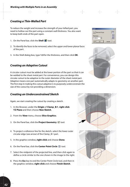
1. On the Panel bar, click the Shell tool.<br />
2. To identify the faces to be removed, select the upper and lower planar faces<br />
of the part.<br />
3. In the Shell dialog box, type 1.5 for the thickness, and then click OK.<br />
Creating an Adaptive Cutout<br />
A circular cutout must be added at the lower portion of the part so that it can<br />
be welded to the sheet metal part. For convenience, you can design this<br />
circular cutout to be adaptive to the outer diameter of the sheet metal part.<br />
Adaptive means one part automatically adapts to geometry on another part.<br />
The first step in making this cutout adaptive is to purposely underconstrain the<br />
size of the cutout by not providing a dimension.<br />
Creating an Underconstrained Sketch<br />
Again, we start creating the cutout by creating a sketch.<br />
1. In the Browser, under the Origin of Clamp_B:1, right-click<br />
YZ Plane and then choose New Sketch.<br />
2. From the View menu, choose Slice Graphics.<br />
3. On the Panel bar, click the Project Geometry tool.<br />
4. To project a reference line for the sketch, select the lower outer<br />
circular edge (see arrow) of the Clamp_B:1 part.<br />
5. In the graphics window, right-click and choose Done.<br />
6. On the Panel bar, click the Center Point Circle tool.<br />
7. Select the midpoint of the projected line, and then click again to<br />
define a circle similar to the one shown in the image to the right.<br />
8. Press the Esc key to end the Center Point Circle tool, and then in<br />
the graphics window, right-click and choose Finish Sketch.<br />
42