1000 Hydraulics Chapter - Ministry of Transportation
1000 Hydraulics Chapter - Ministry of Transportation
1000 Hydraulics Chapter - Ministry of Transportation

You also want an ePaper? Increase the reach of your titles
YUMPU automatically turns print PDFs into web optimized ePapers that Google loves.
BC MoT<br />
SUPPLEMENT TO TAC GEOMETRIC DESIGN GUIDE<br />
MoT Section 1040 TAC Section Not Applicable<br />
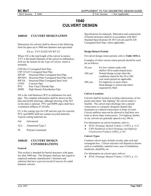
1040<br />
CULVERT DESIGN<br />
1040.01 CULVERT DESIGNATION<br />
Dimensions for culverts shall be shown in the following<br />
form for pipes up to 3000 mm diameter and equivalent:<br />
XX m - YYY Ø ZZZ NN WT CC<br />
Where XX is the total length <strong>of</strong> the culvert in metres;<br />
YYY is the Inside Diameter <strong>of</strong> the culvert in millimetres;<br />
ZZZ are the Initials for the Type <strong>of</strong> Culvert, which is<br />
normally:<br />
CSP 68x13 Corrugated Steel Pipe<br />
CSP 125x25 Corrugated Steel Pipe<br />
SPCSP Structural Plate Corrugated Steel Pipe<br />
SPCSPA Structural Plate Corrugated Steel Pipe Arch<br />
SPCSA Structural Plate Corrugated Steel Arch<br />
CONC Concrete Pipe<br />
PVC Poly Vinyl Chloride Pipe<br />
HDPE High Density Polyethylene Pipe<br />
NN is the wall thickness (WT) in millimetres for steel<br />
pipe. The complete information shall be shown on the<br />
plan and pr<strong>of</strong>ile drawings, although showing <strong>of</strong> the WT<br />
on the plan is optional. PVC and HDPE pipes shall have<br />
a minimum stiffness <strong>of</strong> 320 kPa.<br />
CC is the coating type for CSP and mix type for concrete.<br />
PVC and HDPE shall not contain recycled materials.<br />
Typical coating materials are.<br />
Gal Galvanized<br />
AL2 Aluminized Type 2<br />
PL Polymer Laminated<br />
1040.02 CULVERT DESIGN<br />
CONSIDERATIONS<br />
General<br />
This section is intended for buried structures with spans<br />
less than 3000 mm. The Designer shall pay due regard to<br />
empirical methods, manufacturer’s literature and<br />
solutions that have a proven record <strong>of</strong> success for small<br />
diameter culverts.<br />
Specifications for materials, fabrication and construction<br />
<strong>of</strong> buried structures shall be in accordance with MoT<br />
Standard Specifications SS 303 Culverts and SS 320<br />
Corrugated Steel Pipe, where applicable.<br />
Design Return Periods<br />
For culvert design return periods, refer to Table 1010.A.<br />
Examples <strong>of</strong> when various return periods should be used<br />
are as follows:<br />
50 year For low volume roads with<br />
shallow fill in undeveloped areas.<br />
100 year Normal design except when the<br />
conditions stated for the 50 or 200<br />
year return period are applicable.<br />
200 year For highways in areas where<br />
flood damage is critical and where<br />
requested by MoE.<br />
Culvert Locations<br />
Culverts shall be located at existing watercourses, at low<br />
points and where “day lighting” the culvert outlet is<br />
feasible. The culvert must discharge into a natural<br />
watercourse or a properly designed channel that<br />
terminates at a natural watercourse or body <strong>of</strong> water.<br />
Culvert outflows must not be allowed to find their own<br />
route to down slope watercourses. For highway ditches<br />
in cut, culverts are generally spaced every 300 m.<br />
For information on culvert locations, refer to:<br />
♦ RTAC Drainage Manual Volume 2 (1987), p. 4.12.<br />
♦ CSPI Handbook <strong>of</strong> Steel Drainage and Highway<br />
Construction Products (2002), p.193.<br />
Culvert Types<br />
Common culvert types include circular, pipe arch and<br />
rectangular box. Culvert selection will depend on factors<br />
such as availability, material costs, ease <strong>of</strong> installation,<br />
headroom, durability etc.<br />
For information on culvert types, refer to:<br />
♦ RTAC Drainage Manual Volume 2 (1987), p. 4.3.<br />
June, 2007 Page 1040-1