1000 Hydraulics Chapter - Ministry of Transportation
1000 Hydraulics Chapter - Ministry of Transportation
1000 Hydraulics Chapter - Ministry of Transportation

You also want an ePaper? Increase the reach of your titles
YUMPU automatically turns print PDFs into web optimized ePapers that Google loves.
BC MoT<br />
SUPPLEMENT TO TAC GEOMETRIC DESIGN GUIDE<br />
MoT Section 1040 TAC Section Not Applicable<br />
For culverts less than 3000 mm diameter, a minimum<br />
cover <strong>of</strong> 450 mm (measured from the finished shoulder<br />
grade) over the crown <strong>of</strong> the pipe is required. The<br />
minimum cover requirements may require a sump at the<br />
inlet. An increase in minimum height <strong>of</strong> cover may be<br />
required for heavy construction vehicle loading.<br />
Durability Constraints<br />
If not specified otherwise in a design assignment, the<br />
structural design life <strong>of</strong> a culvert shall be 50 years. The<br />
flow water chemistry is a significant factor relating to the<br />
durability <strong>of</strong> pipe materials; however, economical pipe<br />
materials and coatings are available that perform well in<br />
BC waters. Water hardness, pH and Resistivity values<br />
should be obtained at each site to confirm environmental<br />
conditions. If water resistivity values are 8000<br />
ohm-cm, specialist advice should be obtained. Where<br />
abrasion and corrosion interferes with durability, a<br />
suitable coating or pipe material must be selected. In<br />
some applications, such as creeks with high bed load,<br />
armoured inverts, open bottom arches on concrete<br />
footings or concrete box culverts are recommended.<br />
For information on Durability, refer to:<br />
♦ CSPI Handbook <strong>of</strong> Steel Drainage and Highway<br />
Construction Products (2002), <strong>Chapter</strong> 8;<br />
♦ RTAC Drainage Manual Volume 2 (1987),.<br />
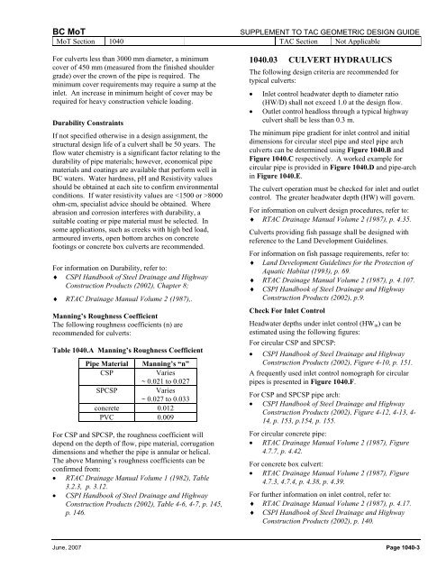
Manning’s Roughness Coefficient<br />
The following roughness coefficients (n) are<br />
recommended for culverts:<br />
Table 1040.A Manning’s Roughness Coefficient<br />
Pipe Material<br />
CSP<br />
SPCSP<br />
Manning’s “n”<br />
Varies<br />
~ 0.021 to 0.027<br />
Varies<br />
~ 0.027 to 0.033<br />
concrete 0.012<br />
PVC 0.009<br />
For CSP and SPCSP, the roughness coefficient will<br />
depend on the depth <strong>of</strong> flow, pipe material, corrugation<br />
dimensions and whether the pipe is annular or helical.<br />
The above Manning’s roughness coefficients can be<br />
confirmed from:<br />
• RTAC Drainage Manual Volume 1 (1982), Table<br />
3.2.3, p. 3.12.<br />
• CSPI Handbook <strong>of</strong> Steel Drainage and Highway<br />
Construction Products (2002), Table 4-6, 4-7, p. 145,<br />
p. 146.<br />
1040.03 CULVERT HYDRAULICS<br />
The following design criteria are recommended for<br />
typical culverts:<br />
• Inlet control headwater depth to diameter ratio<br />
(HW/D) shall not exceed 1.0 at the design flow.<br />
• Outlet control headloss through a typical highway<br />
culvert shall be less than 0.3 m.<br />
The minimum pipe gradient for inlet control and initial<br />
dimensions for circular steel pipe and steel pipe arch<br />
culverts can be determined using Figure 1040.B and<br />
Figure 1040.C respectively. A worked example for<br />
circular pipe is provided in Figure 1040.D and pipe-arch<br />
in Figure 1040.E.<br />
The culvert operation must be checked for inlet and outlet<br />
control. The greater headwater depth (HW) will govern.<br />
For information on culvert design procedures, refer to:<br />
♦ RTAC Drainage Manual Volume 2 (1987), p. 4.35.<br />
Culverts providing fish passage shall be designed with<br />
reference to the Land Development Guidelines.<br />
For information on fish passage requirements, refer to:<br />
♦ Land Development Guidelines for the Protection <strong>of</strong><br />
Aquatic Habitat (1993), p. 69.<br />
♦ RTAC Drainage Manual Volume 2 (1987), p. 4.107.<br />
♦ CSPI Handbook <strong>of</strong> Steel Drainage and Highway<br />
Construction Products (2002), p.9.<br />
Check For Inlet Control<br />
Headwater depths under inlet control (HW in ) can be<br />
estimated using the following figures:<br />
For circular CSP and SPCSP:<br />
• CSPI Handbook <strong>of</strong> Steel Drainage and Highway<br />
Construction Products (2002), Figure 4-10, p. 151.<br />
A frequently used inlet control nomograph for circular<br />
pipes is presented in Figure 1040.F.<br />
For CSP and SPCSP pipe arch:<br />
• CSPI Handbook <strong>of</strong> Steel Drainage and Highway<br />
Construction Products (2002), Figure 4-12, 4-13, 4-<br />
14, p. 153, p.154, p. 155.<br />
For circular concrete pipe:<br />
• RTAC Drainage Manual Volume 2 (1987), Figure<br />
4.7.7, p. 4.42.<br />
For concrete box culvert:<br />
• RTAC Drainage Manual Volume 2 (1987), Figure<br />
4.7.3, 4.7.4, p. 4.38, p. 4.39.<br />
For further information on inlet control, refer to:<br />
♦ RTAC Drainage Manual Volume 2 (1987), p. 4.17.<br />
♦ CSPI Handbook <strong>of</strong> Steel Drainage and Highway<br />
Construction Products (2002), p. 140.<br />
June, 2007 Page 1040-3