1000 Hydraulics Chapter - Ministry of Transportation
1000 Hydraulics Chapter - Ministry of Transportation
1000 Hydraulics Chapter - Ministry of Transportation

You also want an ePaper? Increase the reach of your titles
YUMPU automatically turns print PDFs into web optimized ePapers that Google loves.
BC MoT<br />
SUPPLEMENT TO TAC GEOMETRIC DESIGN GUIDE<br />
MoT Section 1050 TAC Section Not Applicable<br />
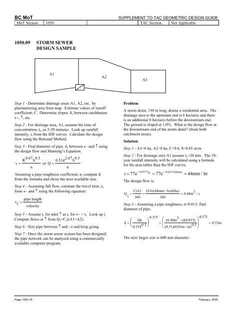
1050.09 STORM SEWER<br />
DESIGN SAMPLE<br />
A1<br />
A2<br />
A3<br />
Step 1 - Determine drainage areas A1, A2, etc. by<br />
planimetering area from map. Estimate values <strong>of</strong> run<strong>of</strong>f<br />
coefficient, C. Determine slopes, S, between catchbasins<br />
←, ↑, etc.<br />
Step 2 - For drainage area, A1, assume the time <strong>of</strong><br />
concentration, t c , as 5-20 minutes. Look up rainfall<br />
intensity, i, from the IDF curves. Calculate the design<br />
flow using the Rational Method.<br />
Step 3 - Find diameter <strong>of</strong> pipe, d, between ← and ↑ using<br />
the design flow and Manning’s Equation.<br />
R 0.67 S 0.5<br />
v = or Q 0.31d2.67 S 0.5<br />
=<br />
n<br />
n<br />
Assuming a pipe roughness coefficient, n, compute d<br />
from the formula and chose the next available size.<br />
Step 4 - Assuming full flow, estimate the travel time, t t ,<br />
from ← and ↑ using the following equation:<br />
pipe length<br />
t t =<br />
velocity<br />
Step 5 - Assume t c for inlet ↑ as t c for ← + t t . Look up i.<br />
Compute flows at ↑ from Q 2 =C 2 i(A1+A2).<br />
Step 6 - Size pipe between ↑ and → and keep going.<br />
Step 7 - Once the storm sewer system has been designed,<br />
the pipe network can be analyzed using a commercially<br />
available computer program.<br />
Problem<br />
A storm drain, 150 m long, drains a residential area. The<br />
drainage area to the upstream end is 6 hectares and there<br />
is an additional 8 hectares before the downstream end.<br />
The ground is sloped at 1.0%. What is the design flow at<br />
the downstream end <strong>of</strong> the storm drain (from both<br />
catchment areas).<br />
Solution<br />
Step 1 - A1=6 ha, A2=8 ha, C=0.6, S=0.01 m/m<br />
Step 2 - For drainage area A1 assume t c =20 min. The 10-<br />
year rainfall intensity will be calculated using a formula<br />
for the area rather than the IDF curves.<br />
−<br />
c<br />
−<br />
i = 77e 0.0277t = 77e 0.0277(20min) = 44mm / hr<br />
The design flow is:<br />
CiA1 (0.6)(44mm / hr)(6ha)<br />
Q = = = 0.44m 3 /s<br />
1 360<br />
360<br />
Step 3 - Assuming a pipe roughness, n=0.013, find<br />
diameter <strong>of</strong> pipe.<br />
0.375<br />
Qn<br />
(0.44m 3 0375 .<br />
/ s)(0.013)<br />
d = ⎛ ⎞ ⎛<br />
⎞<br />
⎜<br />
0.31S 0.5 ⎟ = ⎜<br />
(0.31)(0.01m / m) 0.5 ⎟ = 0.53m<br />
⎝ ⎠ ⎝<br />
⎠<br />
The next larger size is 600 mm diameter.<br />
Page 1050-16 February, 2005