1000 Hydraulics Chapter - Ministry of Transportation
1000 Hydraulics Chapter - Ministry of Transportation
1000 Hydraulics Chapter - Ministry of Transportation

Create successful ePaper yourself
Turn your PDF publications into a flip-book with our unique Google optimized e-Paper software.
BC MoT<br />
SUPPLEMENT TO TAC GEOMETRIC DESIGN GUIDE<br />
MoT Section 1050 TAC Section Not Applicable<br />
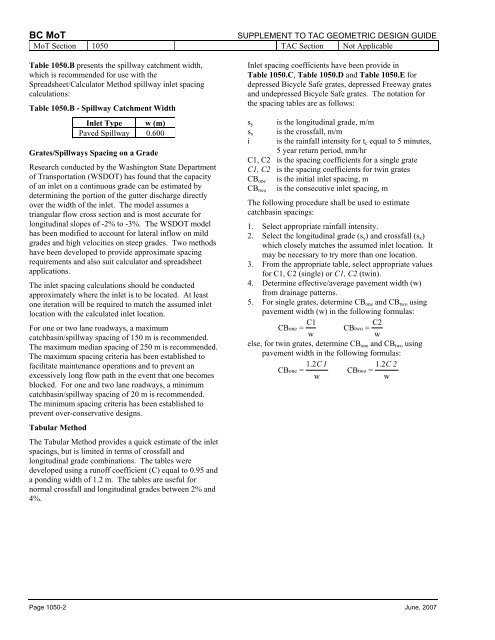
Table 1050.B presents the spillway catchment width,<br />
which is recommended for use with the<br />
Spreadsheet/Calculator Method spillway inlet spacing<br />
calculations:<br />
Table 1050.B - Spillway Catchment Width<br />
Inlet Type w (m)<br />
Paved Spillway 0.600<br />
Grates/Spillways Spacing on a Grade<br />
Research conducted by the Washington State Department<br />
<strong>of</strong> <strong>Transportation</strong> (WSDOT) has found that the capacity<br />
<strong>of</strong> an inlet on a continuous grade can be estimated by<br />
determining the portion <strong>of</strong> the gutter discharge directly<br />
over the width <strong>of</strong> the inlet. The model assumes a<br />
triangular flow cross section and is most accurate for<br />
longitudinal slopes <strong>of</strong> -2% to -3%. The WSDOT model<br />
has been modified to account for lateral inflow on mild<br />
grades and high velocities on steep grades. Two methods<br />
have been developed to provide approximate spacing<br />
requirements and also suit calculator and spreadsheet<br />
applications.<br />
The inlet spacing calculations should be conducted<br />
approximately where the inlet is to be located. At least<br />
one iteration will be required to match the assumed inlet<br />
location with the calculated inlet location.<br />
For one or two lane roadways, a maximum<br />
catchbasin/spillway spacing <strong>of</strong> 150 m is recommended.<br />
The maximum median spacing <strong>of</strong> 250 m is recommended.<br />
The maximum spacing criteria has been established to<br />
facilitate maintenance operations and to prevent an<br />
excessively long flow path in the event that one becomes<br />
blocked. For one and two lane roadways, a minimum<br />
catchbasin/spillway spacing <strong>of</strong> 20 m is recommended.<br />
The minimum spacing criteria has been established to<br />
prevent over-conservative designs.<br />
Tabular Method<br />
The Tabular Method provides a quick estimate <strong>of</strong> the inlet<br />
spacings, but is limited in terms <strong>of</strong> crossfall and<br />
longitudinal grade combinations. The tables were<br />
developed using a run<strong>of</strong>f coefficient (C) equal to 0.95 and<br />
a ponding width <strong>of</strong> 1.2 m. The tables are useful for<br />
normal crossfall and longitudinal grades between 2% and<br />
4%.<br />
Inlet spacing coefficients have been provide in<br />
Table 1050.C, Table 1050.D and Table 1050.E for<br />
depressed Bicycle Safe grates, depressed Freeway grates<br />
and undepressed Bicycle Safe grates. The notation for<br />
the spacing tables are as follows:<br />
s y is the longitudinal grade, m/m<br />
s x is the crossfall, m/m<br />
i is the rainfall intensity for t c equal to 5 minutes,<br />
5 year return period, mm/hr<br />
C1, C2 is the spacing coefficients for a single grate<br />
C1, C2 is the spacing coefficients for twin grates<br />
CB one is the initial inlet spacing, m<br />
CB two is the consecutive inlet spacing, m<br />
The following procedure shall be used to estimate<br />
catchbasin spacings:<br />
1. Select appropriate rainfall intensity.<br />
2. Select the longitudinal grade (s y ) and crossfall (s x )<br />
which closely matches the assumed inlet location. It<br />
may be necessary to try more than one location.<br />
3. From the appropriate table, select appropriate values<br />
for C1, C2 (single) or C1, C2 (twin).<br />
4. Determine effective/average pavement width (w)<br />
from drainage patterns.<br />
5. For single grates, determine CB one and CB two using<br />
pavement width (w) in the following formulas:<br />
CB = C1<br />
one CB = C2<br />
two<br />
w<br />
w<br />
else, for twin grates, determine CB one and CB two using<br />
pavement width in the following formulas:<br />
CB = 1.2 C1<br />
one<br />
CB = 1.2 C2<br />
two<br />
w<br />
w<br />
Page 1050-2 June, 2007