BC MoT SUPPLEMENT TO TAC GEOMETRIC DESIGN GUIDE MoT Section 1040 TAC Section Not Applicable Check For Outlet Control Headloss (H) for full flow conditions can be estimated using the following figures: For circular CSP and SPCSP: • CSPI Handbook <strong>of</strong> Steel Drainage and Highway Construction Products (2002), Figure 4-17, 4-18, p. 158, p. 159. For CSP and SPCSP pipe arch: • CSPI Handbook <strong>of</strong> Steel Drainage and Highway Construction Products (2002), Figure4-19, 4-20, p. 160, p. 161. For circular concrete pipe: • RTAC Drainage Manual Volume 2 (1987), Figure 4.7.14, p. 4.48. For concrete box culvert: • RTAC Drainage Manual Volume 2 (1987), Figure 4.7.13, p. 4.47. Headloss (H) for partially full flow conditions can be approximated using the equation from the CSPI Handbook <strong>of</strong> Steel Drainage and Highway Construction Products (2002), p. 146, or equation 4.5.4 from the RTAC Drainage Manual Volume 2 (1987), p. 4.18. The headwater depth under outlet control (HW out ) can be estimated using CSPI Handbook <strong>of</strong> Steel Drainage and Highway Construction Products (2002), p. 143, or equation 4.5.10 from the RTAC Drainage Manual Volume 2 (1987), p. 4.20. For information on outlet control, refer to: ♦ RTAC Drainage Manual Volume 2 (1987), p. 4.18. ♦ CSPI Handbook <strong>of</strong> Steel Drainage and Highway Construction Products (2002), p. 143. Hydraulic Programs Hydraulic computer programs have distinct advantages over hand calculations or nomographs for determining normal depth, culvert velocity, hydraulic radius and area <strong>of</strong> flow for partially full flow conditions. • CSPI Handbook <strong>of</strong> Steel Drainage and Highway Construction Products (2002), p. 150. Critical Flow For information on critical flow, refer to Section 1030.03. Treatment <strong>of</strong> Inlet/Outlet Structures Riprap, in combination with geotextile, is generally used for inlet and outlet protection. The average culvert velocity during the design flow should be used to determine riprap requirements. For information on riprap lining and filter blanket, refer to Section 1030.04. To prevent scour around the inlet and outlet, riprap shall be placed in the channel bed and side slopes. The length <strong>of</strong> the inlet apron should be at least equal to twice the culvert rise while the length <strong>of</strong> the outlet apron should be at least equal to four times the culvert rise. The riprap should be placed to a height <strong>of</strong> at least 0.3 m above the high water level (HWL) or above the crown <strong>of</strong> the pipe, whichever is higher. For information and details on concrete inlet and outlet structures, refer to: ♦ Specification Dwg. No. SP303-01 to 04, MoT Standard Specifications for Highway Construction. ♦ RTAC Drainage Manual Volume 2 (1987), p. 4.25 and 4.103. ♦ CSPI Handbook <strong>of</strong> Steel Drainage and Highway Construction Products (2002), p.300. Page 1040-4 June, 2007
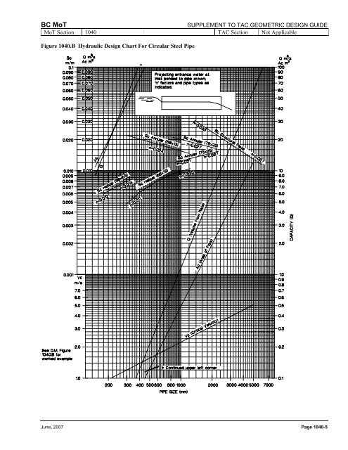
BC MoT SUPPLEMENT TO TAC GEOMETRIC DESIGN GUIDE MoT Section 1040 TAC Section Not Applicable Figure 1040.B Hydraulic Design Chart For Circular Steel Pipe June, 2007 Page 1040-5